Hand pump and hydraulic brake

A hand pump and hydraulic technology, applied in the direction of pumps, piston pumps, pump devices, etc., to achieve the effect of reducing labor intensity

Pending Publication Date: 2020-01-07
BEIJING IWHR BIC
View PDF0 Cites 0 Cited by
  • Summary
  • Abstract
  • Description
  • Claims
  • Application Information

AI Technical Summary

Problems solved by technology

[0006] The invention provides a hand pump and a hydraulic gate to solve the problem that the existing hydraulic gate cannot lift the gate without electricity

Method used


Image

  • Hand pump and hydraulic brake
  • Hand pump and hydraulic brake
  • Hand pump and hydraulic brake

Examples


Embodiment 1

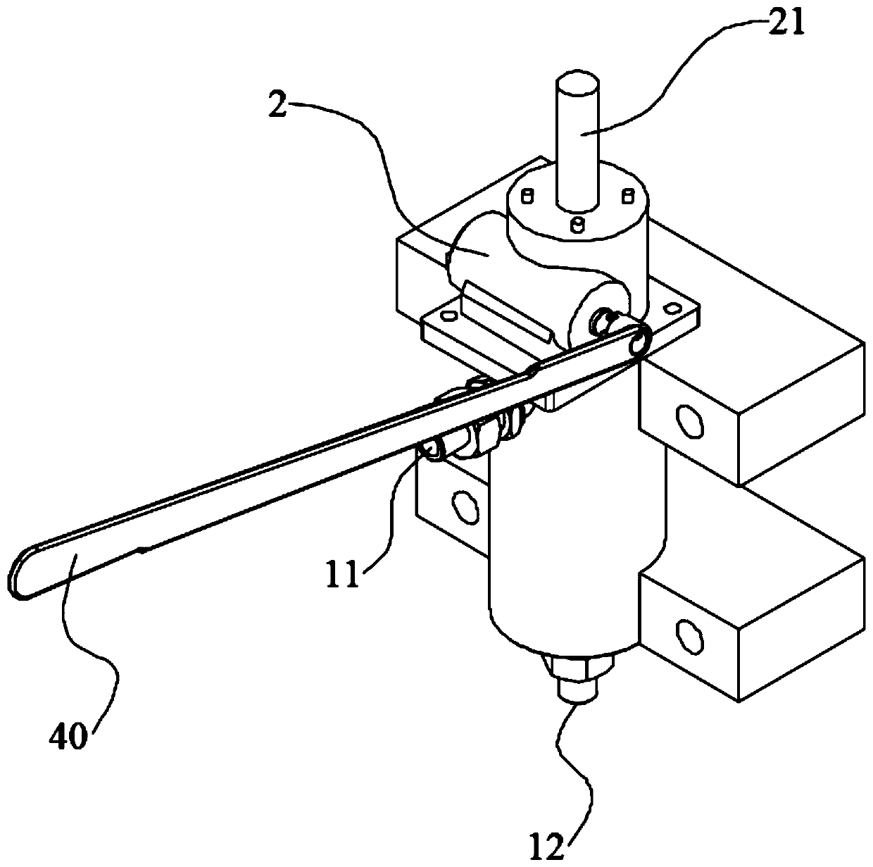
[0075] Such as figure 1 As shown, it is a schematic structural diagram of a hand pump provided in Embodiment 1 of the present invention. The hand pump includes a housing, an oil inlet 11 and an oil outlet 12 arranged on the housing, wherein:

[0076] The housing houses the piston ( figure 1Not shown in ), the piston is located between the oil inlet 11 and the oil outlet 12, and is used to make the housing oil in and out. The casing is also connected with a variable speed booster structure 2, and the variable speed booster structure 2 is used to drive the piston to move. Optionally, the variable speed booster structure 2 and the casing are assembled separately to facilitate the shaping of the hand pump. The hand pump provided by the present invention utilizes the variable-speed booster structure 2 to move the piston, which reduces the labor intensity of the workers. This not only solves the problem that the existing hydraulic gates cannot be lifted and lowered without electr...

Embodiment 2

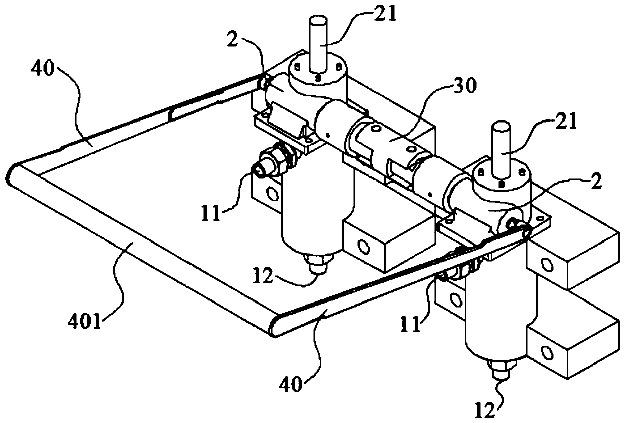
[0080] Such as figure 2 As shown, it is a schematic structural diagram of a hand pump provided in Embodiment 2 of the present invention. The difference between the hand pump provided in Embodiment 2 and the hand pump provided in Embodiment 1 is that the number of hand pumps is two or more ( figure 2 Only two hand pumps are shown). In the second embodiment, the worm gears of two adjacent hand pumps are connected by a coupling 30, so that different hand pumps form a unified whole, that is, by turning the worm gear of one of the hand pumps, the other hand pumps can be driven. The worm gear of the pump rotates.

[0081] Further, when there are two or more hand pumps, the worm gears of the two outermost hand pumps are also connected with a hand crank 40 . The worm gears of all the hand pumps can be conveniently rotated by arranging the hand rocker 40 on the two outermost hand pumps.

[0082] Furthermore, a connecting piece 401 is also connected between the ends of the two han...

Embodiment 3

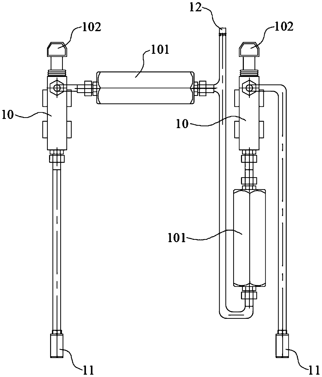
[0084] Such as image 3 As shown, it is a schematic structural diagram of a hand pump provided in Embodiment 3 of the present invention. The working principle of the hand pump in the third embodiment is different from the hand pumps in the first and second embodiments, but they both realize the entry and exit of hydraulic oil through the movement of the piston. In the third embodiment, the hand pump includes two hydraulic pumps 10 arranged in parallel. The hand pump is provided with two oil inlets 11 and one oil outlet 12. The two hydraulic pumps 10 are respectively connected to the two oil inlets. 11, and are commonly connected to the oil outlet 12; a first check valve 101 is provided between each hydraulic pump 10 and the oil outlet 12, and each hydraulic pump 10 is provided with a control rod 102 for controlling the entry and exit of hydraulic oil ; At the same time, control the rise or fall of the control lever 102, which can make one of the oil inlet 11 oil in, and the o...


PUM


Abstract

The invention relates to the technical field of water conservancy projects, in particular to a hand pump and a hydraulic brake. The hand pump comprises an oil inlet, an oil outlet, a piston, and a variable-speed power-enhanced structure, wherein the piston is located between the oil inlet and the oil outlet; and the variable-speed power-enhanced structure is used for driving the piston to move. According to the hand pump provided by the invention, the variable-speed power-enhanced structure is utilized for driving the piston to move, so that the labor intensity of workers is reduced, not onlyis the problem that the lifting of a gate of an existing hydraulic brake cannot be realized without electricity solved, but also oil can be fed and discharged easily through the hand pump by the workers, and the gate can be lifted up and lowered won by using manpower.

Description

technical field [0001] The invention relates to the technical field of water conservancy engineering, in particular to a hand pump and a hydraulic gate. Background technique [0002] Hydraulic gates used in water conservancy projects are generally driven by power generated by hydraulic pressure. [0003] In related technologies, the flow of hydraulic pressure generally requires a power source such as a motor and an oil pump to drive a hydraulic station to generate hydraulic pressure to realize the expansion and contraction of the oil cylinder, thereby controlling the lift of the gate. [0004] In some remote mountainous areas, due to the lack of electricity in remote mountainous areas, the traditional drive system cannot rely on the energy generated by the hydraulic station to lift and lower the gate without electricity. When the upstream river and reservoir need to store water, if the gate is not raised in time, it will cause waste of water storage in the upstream river or...

Claims


Application Information

Patent Timeline
Patent Type & Authority Applications(China)
IPC IPC(8): F15B13/02F15B11/08F04B9/14F04B9/02F04B23/06
CPCF04B9/02F04B9/14F04B23/06F15B11/08F15B13/02
Inventor 陈晏育赵建华刘杰耿晔晗王湛闫永生
Owner BEIJING IWHR BIC
Why Eureka
Try Eureka