Eureka AIR delivers breakthrough ideas for toughest innovation challenges, trusted by R&D personnel around the world.

Shaft, pump body component and compressor

A main body, short shaft technology, applied in pump components, liquid fuel engines, components of pumping devices for elastic fluids, etc., can solve the problems of reduced reliability, damage, component wear and other problems of compressors, and reduce eddy current phenomenon. , Improve the lubricating effect and the effect of increasing the oil volume of the pump

Pending Publication Date: 2019-01-11
ZHUHAI LANDA COMPRESSOR +1
View PDF0 Cites 0 Cited by
  • Summary
  • Abstract
  • Description
  • Claims
  • Application Information

AI Technical Summary

Problems solved by technology

[0004] If oil reduction is carried out in response to the national policy, the pump body of the compressor is insufficiently lubricated, so the pump body needs to be moved down. If the pump body is moved down, it is very easy to generate eddy currents at the lower end of the crankshaft, which increases the flow resistance of the refrigerating oil, thereby The refrigeration oil cannot be fully utilized and sent to the parts that need lubrication, resulting in insufficient lubrication of the components in the compressor, resulting in wear or even damage to the components, reducing the reliability of the compressor

Method used


Image

  • Shaft, pump body component and compressor
  • Shaft, pump body component and compressor
  • Shaft, pump body component and compressor

Examples


Embodiment 1

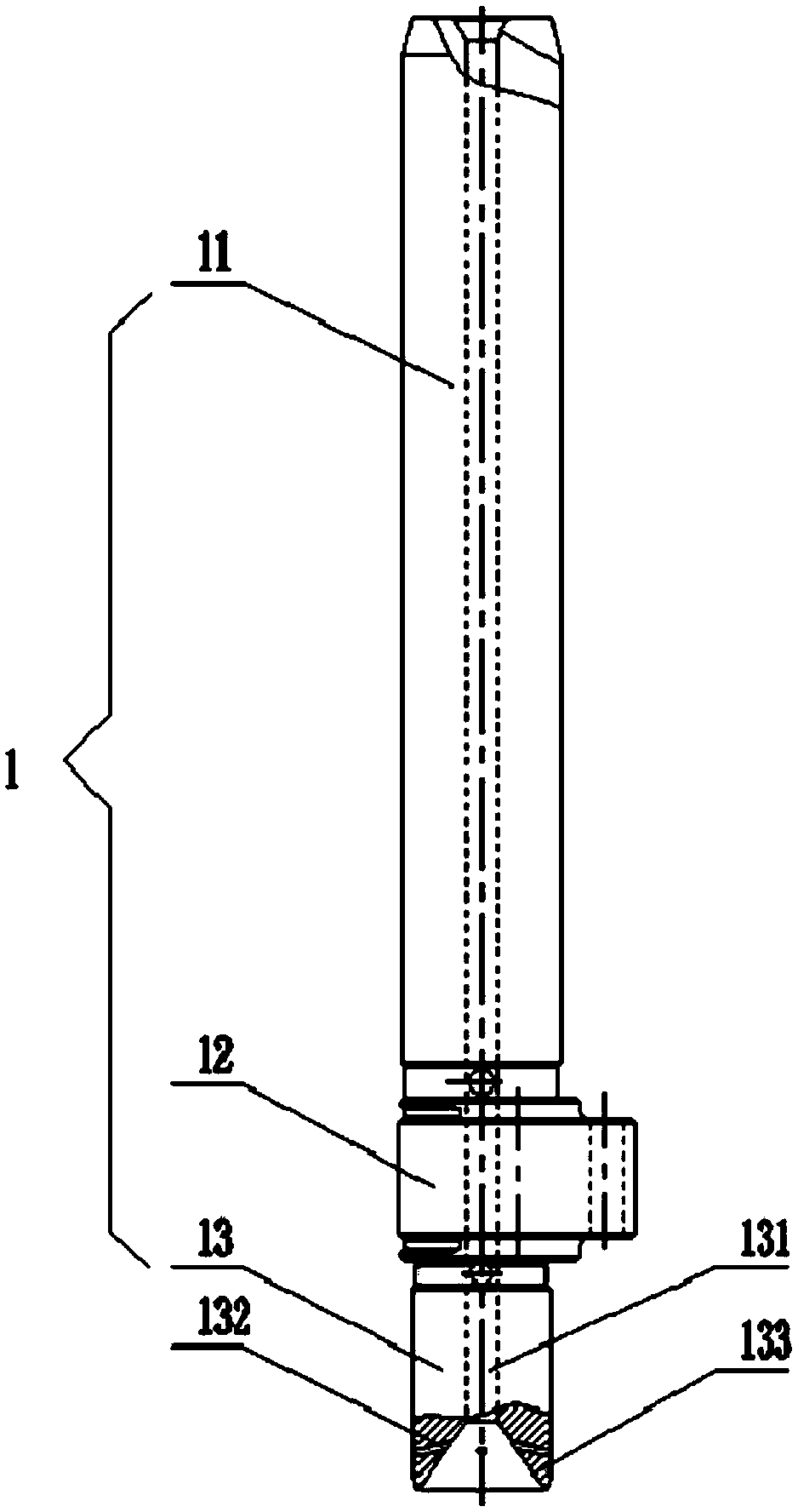
[0040] Such as figure 2 As shown, the present invention provides a shaft, including: a shaft body 1 and an oil pumping structure arranged on the shaft body 1 .

[0041] Such as figure 2 As shown, the first end of the central shaft body 1 of the present invention is placed in the lubricating medium 3, and the second end is connected to the rotating power source, which may be the output end of the rotating torque of the rotating motor.

[0042] Such as figure 2 As shown, the oil pump structure in the present invention includes an oil delivery main hole 131 arranged axially on the end face of the first end of the shaft body 1, and an outer circumference of the first end of the shaft body 1 Several enhanced oil pumping holes 132 are opened on the wall, and the first end of the enhanced oil pumping hole 132 communicates with the main oil delivery hole 131 , and the second end penetrates the outer peripheral wall of the first end of the shaft body 1 . In the present invention, t...

Embodiment 2

[0053] The present invention also provides a pump body assembly, including a crankshaft, which is the shaft in Embodiment 1.

Embodiment 3

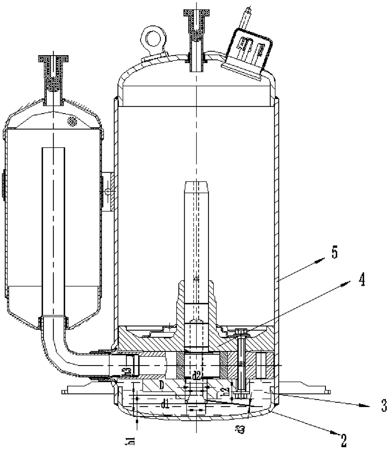
[0055] Such as image 3 As shown, the present invention also provides a compressor, including the pump body assembly 4 in Embodiment 2. It also includes a lower cover 2 and a housing 5 . The pump body assembly 4, the lower cover 2, and the housing 5 form a closed volume, and liquid lubricating oil is placed in the closed volume.


PUM


Abstract

The invention provides a shaft, a pump body component and a compressor. By means of the shaft, the pump body component and the compressor, the problem that eddy is prone to being generated at a compressor crankshaft oil pumping inlet to increase the oil pumping resistance is solved. The adopted technical scheme of the shaft comprises a shaft body and an oil pumping structure, wherein a first end of the shaft body is placed in a lubricating medium; and the oil pumping structure comprises an oil conveying main hole passage which is arranged in the end face of the first end of the shaft body andarranged in the axial direction and a plurality of strengthening oil pumping hole passages arranged in the periphery wall of the first end of the shaft body, first ends of the strengthening oil pumping hole passages communicate with the oil conveying main hole passage, and second ends of the strengthening oil pumping hole passages penetrate through the periphery wall of the first end of the shaftbody. According to the shaft, the pump body component and the compressor, the strengthening oil pumping hole passages connect the oil conveying main hole passage with the periphery wall of the first end of the shaft body and form partial tension near the first end of the shaft body, when the shaft body rotates under driving of a rotating power source, agitation of the shaft on the lubricating medium can be effectively reduced, occurrence of an eddy phenomenon is reduced, and then the lubricating effect is improved.

Description

technical field [0001] The invention relates to the technical field of compressors, in particular to a shaft, a pump body assembly and a compressor. Background technique [0002] At present, the country's oil imports are increasingly dependent on imports, and the supply of oil products is interrupted at any time, which in turn affects the development of the country. In order to ensure sufficient lubrication and reliability of the compressor, the compressor needs to inject a large amount of refrigeration oil, which is contrary to the national development strategy. In order to meet the national development, the reduction or replacement of compressor refrigeration oil has become a major development trend. [0003] The crankshaft of the rotary compressor includes a long shaft, an eccentric shaft and a short shaft arranged in sequence from top to bottom. The eccentric part is placed in the inner cavity of the cylinder of the compressor pump body. The crankshaft moves concentric...

Claims


Application Information

Patent Timeline
IPC IPC(8): F04C29/00F04C29/02
CPCF04C29/00F04C29/023F04C2240/603
Inventor 程剑国丁学超张洪钰伍文轩彭小涛
Owner ZHUHAI LANDA COMPRESSOR
Why Eureka
Eureka Blog
Learn More