Electron beam evaporation coating machine coating film correcting device

A technology of electron beam evaporation and coating machine, which is applied in the directions of vacuum evaporation coating, ion implantation coating, sputtering coating, etc., which can solve the problems that are difficult to meet at the same time, and the influence of the cavity pumping coating uniformity is not considered. Achieve the effect of small structural limitations, simple structure and good effect

Pending Publication Date: 2019-04-12
湖南宇诚精密科技有限公司
View PDF0 Cites 2 Cited by
  • Summary
  • Abstract
  • Description
  • Claims
  • Application Information

AI Technical Summary

Problems solved by technology

[0002] The correction device of the existing coating machine usually adopts four fixed correction devices and one vertical movable correction device. The fixed correction method does not consider the influence of chamber pumping on the uniformity of the coating, and the vertical movable correction device must ensure the correctness of the correction plate and the evaporation source. It is often difficult to satisfy both the relative height and the vertical movement space structurally.

Method used


Image

  • Electron beam evaporation coating machine coating film correcting device
  • Electron beam evaporation coating machine coating film correcting device

Examples


Embodiment

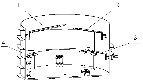
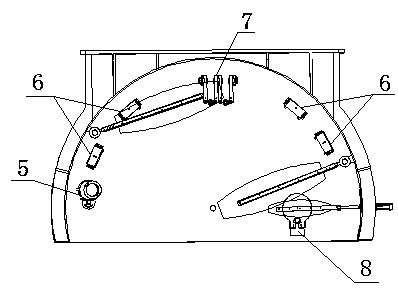
[0019] refer to Figure 1-Figure 2 , a coating correction device for an electron beam evaporation coating machine, including a fixed correction device I1, a fixed correction device II2, a movable correction device 3, an evaporation source 7, four halogen lamps 6, an ion source 5, and an electron gun 8 , the fixed correction device I1, the fixed correction device II2 and the movable correction device 3 are all fixed on the furnace body 4 of the coating machine;

[0020] The 1 evaporation source 7, the 4 halogen lamps 6, and the 1 ion source 5 are on the same graduation circle, and the 4 halogen lamps 6 are divided into two groups, which are symmetrical on both sides along the central position; the evaporation source 7 is located at a symmetrical position in the center of the furnace body, close to the air outlet of the furnace body; the ion source 5 is located on the left side of the furnace body close to the furnace door; the electron gun 8 is located on the right side of the ...


PUM


Abstract

The invention relates to an electron beam evaporation coating machine coating film correcting device which comprises a fixed correcting device I, a fixed correcting device II, a movable correcting device, one evaporation source, four halogen lamps, one ion source and one electronic gun. The one evaporation source, the four halogen lamps and the one ion source are on one same divided circle; the four halogen lamps are divided into two groups and are symmetrical along two sides of the center position; the evaporation source is located in the central symmetry position of a furnace body; the ion source is located on the left side of the furnace body; the electronic gun is located on the right side of the furnace body; the fixed correcting device I is located in the middle position between thetwo halogen lamps on the left side, and is arranged on the inner wall of the furnace body; the fixed correcting device II is located in the middle position between the halogen lamps on the right sideand the electronic gun, and is arranged on the inner wall of the furnace body; the installation heights of the fixed correcting device I and the fixed correcting device II are consistent; and the movable fixed correcting device is located on the right side of the furnace body and is located above the electronic gun. The electron beam evaporation coating machine coating film correcting device provided by the invention has the advantages of simple structure, less number of correcting devices, good effect and the like.

Description

technical field [0001] The invention relates to a coating correction device for an electron beam evaporation coating machine. Background technique [0002] The correction device of the existing coating machine usually adopts four fixed correction devices and one vertical movable correction device. The fixed correction method does not consider the influence of chamber pumping on the uniformity of the coating, and the vertical movable correction device must ensure the correctness of the correction plate and the evaporation source. It is often difficult to satisfy both the relative height and the vertical movement space structurally. Contents of the invention [0003] The calculation problem to be solved by the present invention is to provide a coating correction device for an electron beam evaporation coating machine with a simple structure, a small number of correction devices, good effect and a wider application range. [0004] The technical solution adopted by the presen...

Claims


Application Information

Patent Timeline
IPC IPC(8): C23C14/30C23C14/54
CPCC23C14/30C23C14/542C23C14/543
Inventor 杨佳葳龚涛蔡国龚平谢俊
Owner 湖南宇诚精密科技有限公司
Why Eureka
Try Eureka