
Discharge circuit, power supply and display device

A technology of discharge circuit and discharge path, which is applied in the field of power supply and display device and discharge circuit, and can solve the problems of afterimage after shutdown, time-consuming, and load stability reduction, etc.

Active Publication Date: 2021-09-14
KUSN INFOVISION OPTOELECTRONICS
View PDF7 Cites 0 Cited by
  • Summary
  • Abstract
  • Description
  • Claims
  • Application Information

AI Technical Summary

Problems solved by technology

However, in the actual working process of the power supply, the process of converting the logic power supply Vin from high level to low level takes a certain amount of time, such as Figure 2a As shown, the charge on the equivalent capacitance C of the power supply is released to the reference ground through the circuit resistance R0, and the discharge path is shown in the direction of the arrow in the figure
Figure 2b Taking the power supply of the liquid crystal display module as an example, the discharge sequence diagram of the power supply is shown. The discharge time Δt required for the logic power supply Vin to discharge from 0.9Vin to 0.1Vin is about 470ms, and the discharge time Δt is much greater than the 10ms required by the VESA standard. If the time is too long, and the discharge time is uncontrollable, it will easily cause problems such as after-image after shutdown and reduced load stability.

Method used


Image

  • Discharge circuit, power supply and display device
  • Discharge circuit, power supply and display device
  • Discharge circuit, power supply and display device

Examples


Embodiment Construction

[0029] Various embodiments of the invention will be described in more detail below with reference to the accompanying drawings. In the various drawings, the same elements are denoted by the same or similar reference numerals. For the sake of clarity, various parts in the drawings have not been drawn to scale.

[0030] The specific implementation manners of the present invention will be further described in detail below in conjunction with the accompanying drawings and embodiments.

[0031] Figures 3a to 3f respectively shows the discharge timing diagram of the conventional power supply, Figure 3a Taking the power supply of the liquid crystal display module as an example, the discharge timing diagram of the traditional power supply is shown. Figure 3a The dotted line part shows the timing diagram of natural discharge after the capacitor is charged to 3.3V, where the resistor is 2.67kΩ and the capacitor is 70μF. Different from the natural discharge process of capacitors, ...


PUM


Abstract

The application discloses a discharge circuit, a power supply and a display device. The discharge circuit includes: a voltage divider circuit, used to provide a control signal according to the driving signal; a first resistor, used to receive the input power; and a switch tube, the control end of the switch tube receives the control signal, and the first channel end is connected to the first resistor , the second access end is connected to the reference ground, and the switch tube is used to provide a discharge path from the input power to the reference ground according to the control signal, wherein the resistance value of the first resistor is selected according to the expected discharge time of the input power, and the driving signal is on The voltage value in the power state is less than or equal to zero, and rises when the power is off to make the control signal turn on the switch tube. The discharge circuit provides a discharge path from the input power to the reference ground, and controls the discharge time of the input power by controlling the size of the first resistor, so that the input power can be quickly discharged, the stability of the load is improved, and the problem of afterimage after shutdown is avoided.

Description

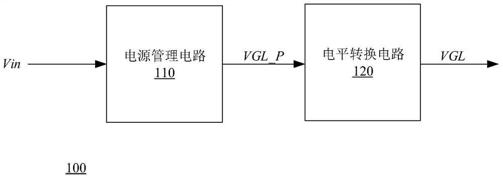
technical field [0001] The present invention relates to the field of display technology, and more specifically, to a discharge circuit, a power supply and a display device. Background technique [0002] With the popularity of electronic products, power supplies are used in various electronic products. The response time of the power supply is an important parameter. For example, the Video Electronics Standards Association (VESA) standard requires that the power-off time of the display device be controlled within 10 ms, so as to effectively eliminate afterimages. [0003] In the existing technology, such as figure 1 As shown, the power supply 100 includes a power management circuit 110 and a level conversion circuit 120. The power management circuit 110 is used to receive the logic power Vin and provide the initial signal VGL_P required by the load. The level conversion circuit 120 provides the power management circuit 110 with The initial signal is level converted to obtain...

Claims


Application Information

Patent Timeline
Patent Type & Authority Patents(China)
IPC IPC(8): H02M1/32
CPCH02M1/32H02M1/322
Inventor 韩小伟田申刘洪海
Owner KUSN INFOVISION OPTOELECTRONICS
Learn More