Fuel cell system

一种燃料电池系统、燃料电池的技术,应用在燃料电池、燃料电池助剂、运输燃料电池技术等方向,能够解决蓄电池过度充电等问题

Active Publication Date: 2010-08-04
TOYOTA JIDOSHA KK
View PDF1 Cites 6 Cited by
  • Summary
  • Abstract
  • Description
  • Claims
  • Application Information

AI Technical Summary

Problems solved by technology

Although the remaining power is charged to the battery, there is a concern that the battery will be overcharged if the charging capacity of the battery is reduced due to the low temperature environment.

Method used


Image

  • Fuel cell system
  • Fuel cell system
  • Fuel cell system

Examples


Embodiment Construction

[0031] Hereinafter, embodiments of the present invention will be described with reference to the drawings.

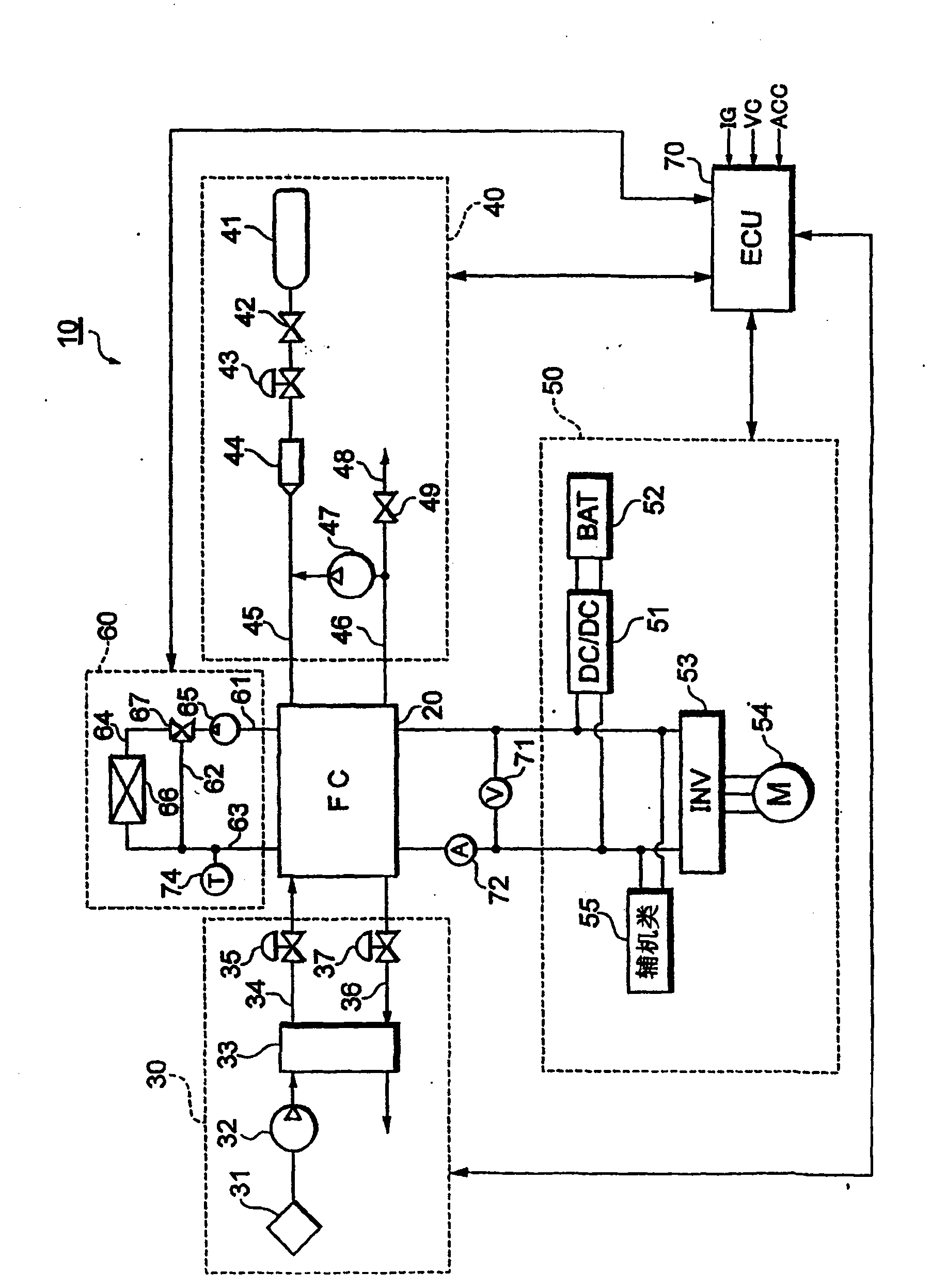
[0032] figure 1 The system configuration of the fuel cell system 10 of this embodiment is shown.

[0033] The fuel cell system 10 functions as an on-board power supply system mounted on a fuel cell vehicle, and includes a fuel cell stack 20 that receives supply of reactive gas (fuel gas, oxidizing gas) to generate power, and supplies the fuel cell stack 20 as an oxidizer. An oxidizing gas supply system 30 for gaseous air, a fuel gas supply system 40 for supplying hydrogen as a fuel gas to the fuel cell stack 20, a power system 50 for controlling the charge and discharge of power, and a power system for controlling the fuel cell stack 20 A cooling system 60 for cooling, and a control unit (ECU) 70 that controls the entire system.

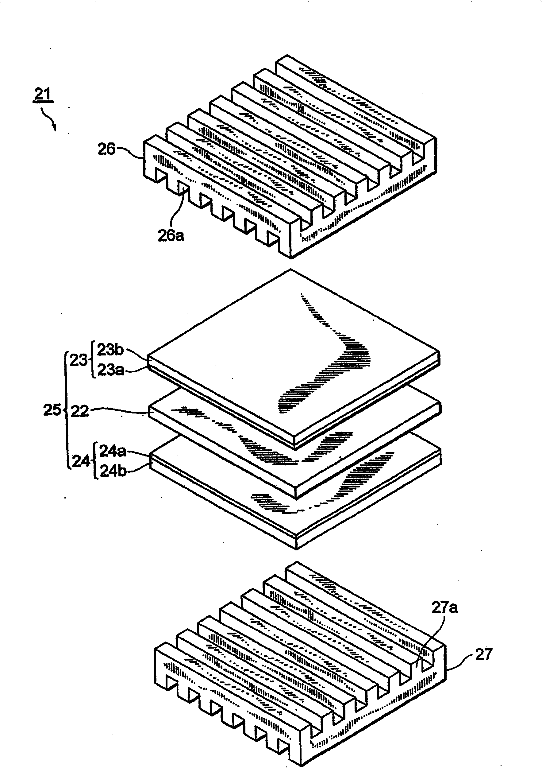
[0034] The fuel cell stack 20 is a solid polymer electrolyte battery stack in which a plurality of unit cells are stacked in series. In the fuel c...


PUM


Abstract

Provided is a fuel cell system, in which the capacity component of a fuel cell is charged with an excess power (Ws) corresponding to the difference between the generation quantity (Pmes) of the fuel cell and a generation command value (Pref) by raising the output voltage of the fuel cell, if a generation command value (Pref) to the fuel cell is abruptly reduced while the fuel cell is being warmed by a low-efficiency run having a generation efficiency lower than that of the ordinary run. The fuel cell system equalizes an electric power (Pmes - Ws) to be fed to an external load of the fuel cell and the generation command value (Pref). As a result, the control can be made not to feed the excess power to the external load when the electric power requested on the fuel cell abruptly drops at the low-efficiency run.

Description

Technical field [0001] The present invention relates to a fuel cell system that uses low-efficiency operation to preheat a fuel cell. Background technique [0002] A fuel cell is a power generation system that directly converts the energy released by the oxidation reaction into electrical energy by oxidizing fuel through an electrochemical process. It has a stacked structure in which a plurality of membrane-electrode assemblies are stacked. The membrane-electrode assembly A pair of electrodes made of a porous material sandwich both sides of an electrolyte membrane for selectively transporting hydrogen ions. Among them, a solid polymer electrolyte fuel cell using a solid polymer membrane as an electrolyte is low in cost, easy to miniaturize, and has a high output density, so it is expected to be used as an on-board power source. [0003] This type of fuel cell usually regards 70 to 80°C as the optimal temperature region for power generation. However, in environments such as cold re...

Claims


Application Information

Patent Timeline
Patent Type & Authority Applications(China)
IPC IPC(8): H01M8/04H01M8/00H01M8/10
CPCH01M8/04619Y02T90/32H01M2250/20H01M8/0488H01M8/04223Y02E60/50Y02T90/40H01M8/04225
Inventor 今西启之真锅晃太小川朋也
Owner TOYOTA JIDOSHA KK
Why Eureka
Try Eureka