Control circuit with multiple power sources

a control circuit and power source technology, applied in the field of control circuits, can solve problems such as the inability to meet the requirement of 1

Active Publication Date: 2006-10-31
WINBOND ELECTRONICS CORP
View PDF5 Cites 8 Cited by
  • Summary
  • Abstract
  • Description
  • Claims
  • Application Information

AI Technical Summary

Benefits of technology

[0007]The main purpose of present invention is providing a control circuit with multiple power sources, which is able to adjust the output voltage dynamically to keep the substrate voltage of PMOS at the highest voltage value inside the chip without any leakage current. And, this control circuit is also able to output the first voltage potential and the second voltage potential for different usages of different circuits.

Problems solved by technology

But for some applications that need to generate two different output voltages to control different circuits, the circuit in FIG. 1 cannot reach this requirement because of its only one output voltage.

Method used


Image

  • Control circuit with multiple power sources
  • Control circuit with multiple power sources
  • Control circuit with multiple power sources

Examples


Embodiment Construction

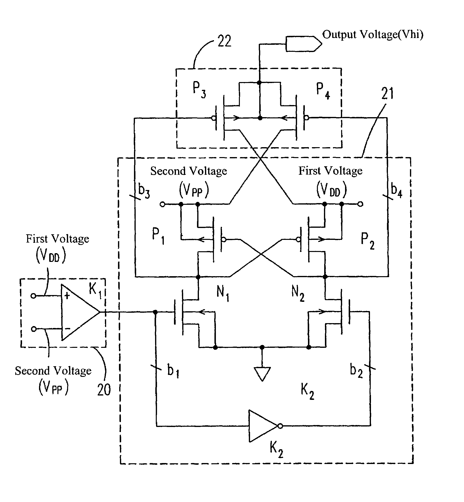
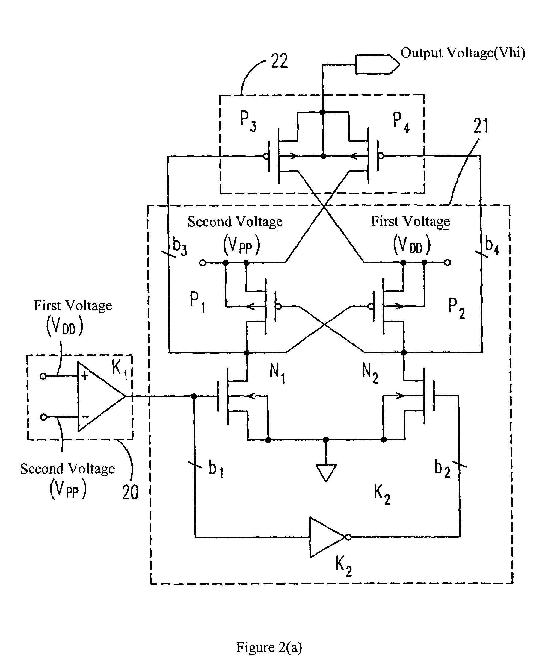
[0023]Please refer FIG. 2(a), which shows the circuit of present example with better solution. The present invention provides a control circuit with multiple power sources, which accepts the voltage compared between the first input voltage Vdd (which is a voltage source that is provided by the power supplier outsides the LCD driver) and the second input voltage Vpp (which is a voltage source that is generated by the internal circuit of the insides the LCD driver) by a Comparator Circuit 20 and generates an output signal. This control circuit with multiple power sources contains a Voltage Transferring Circuit 21 and an Output Circuit 22.

[0024]This Voltage Transferring Circuit 21 connects to the Comparator Circuit 20 and accepts the first input voltage Vdd and the second input voltage Vpp, to react the control of the output signal and to generate the first voltage potential and the second voltage potential. And this Voltage Transferring Circuit 21 can comprise one inverter, two PMOS, ...


PUM


Abstract

The present invention provides a control circuit with multiple power sources, which accepts an output signal from a comparator circuit. This control circuit with multiple power sources contains two components: one is a voltage transferring circuit, which connects to the comparator and accepts the first and the second input voltages to react the controls of respective output signals for generating the first voltage potential and the second voltage potential; another is an output circuit, which connects to the voltage transferring circuit to react the controls of the first voltage potential and the second voltage potential for deciding the correct output from the first input voltage or the second input voltage.

Description

FIELD OF THE INVENTION[0001]The present invention is relative to a control circuit, especially for a control circuit with multiple power sources.BACKGROUND OF THE INVENTION[0002]There are two main power sources of a LCD Driver (Liquid Crystal Display Driver): one is provided by an external power supplier for voltage Vdd, and another is generated by the LCD's internal circuit for voltage Vpp. And, the substrate voltage of the chip's PMOS inside the LCD driver must be higher than the voltages of source electrode and drain electrode, or the heavy leakage current will go through the source electrode or drain electrode to the substrate of PMOS to destroy the chip.[0003]But in current general LCD driver's internal circuit, the output voltage is usually higher than the voltage that the power supplier provides after a period of running time. And for some applications of consumptive products, the output voltage of a running LCD driver may be higher or lower than the voltage that the power su...

Claims


Application Information

Patent Timeline
Patent Type & Authority Patents(United States)
IPC IPC(8): H02J1/00G09G3/36H02J1/08H03K3/356H03K17/693
CPCG09G3/3611H02J1/08H03K3/356113H03K17/693G09G2300/0408G09G2330/02
Inventor WU, LI-TEWANG, HSI-YUAN
Owner WINBOND ELECTRONICS CORP
Why Eureka
Try Eureka