Signal driving system

Inactive Publication Date: 2005-03-17
AVAGO TECH WIRELESS IP SINGAPORE PTE
View PDF4 Cites 7 Cited by
  • Summary
  • Abstract
  • Description
  • Claims
  • Application Information

AI Technical Summary

Benefits of technology

[0008] The present invention provides a signal driving system, which includes the following elements. A first driver is coupled to a first voltage supply. The first driver is configured to push a signal through an output node via a current mirror. The current mirror is coupled to a second voltage supply. The second voltage supply has a higher voltage value than the first voltage supply. A first protection device is coupled between the first driver and the current mi

Problems solved by technology

For example, producing a differential output signal with a signal driving system may not possible when the maximum supply voltage is equal to or less than the common-mode output voltage that is determined by external sources.
In this case the signal driving system is unable to drive the differentia

Method used


Image

  • Signal driving system
  • Signal driving system
  • Signal driving system

Examples


Embodiment Construction

[0016] Overview

[0017] While specific configurations and arrangements are discussed, it should be understood that this is done for illustrative purposes only. A person skilled in the pertinent art will recognize that other configurations and arrangements can be used without departing from the spirit and scope of the present invention. It will be apparent to a person skilled in the pertinent art that this invention can also be employed in a variety of other applications.

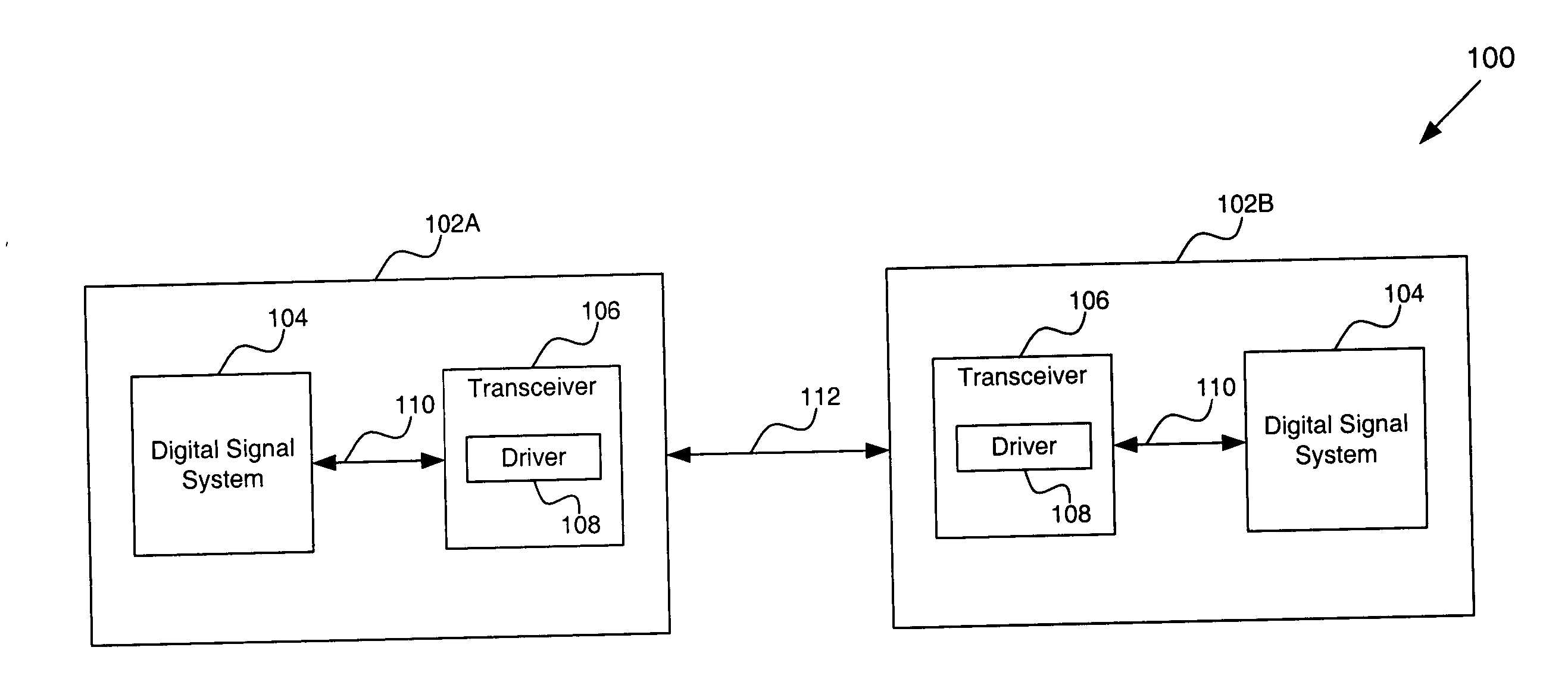
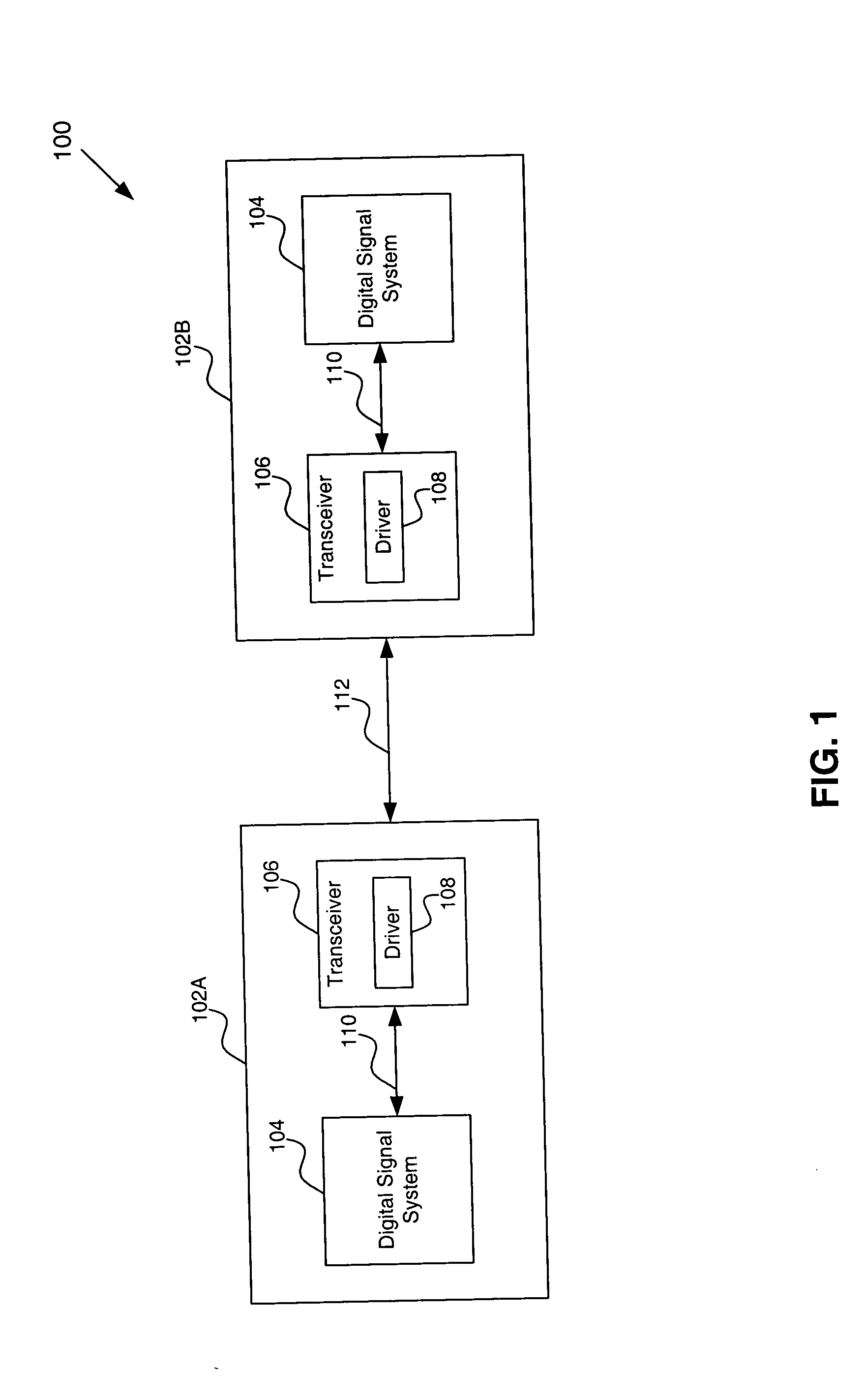
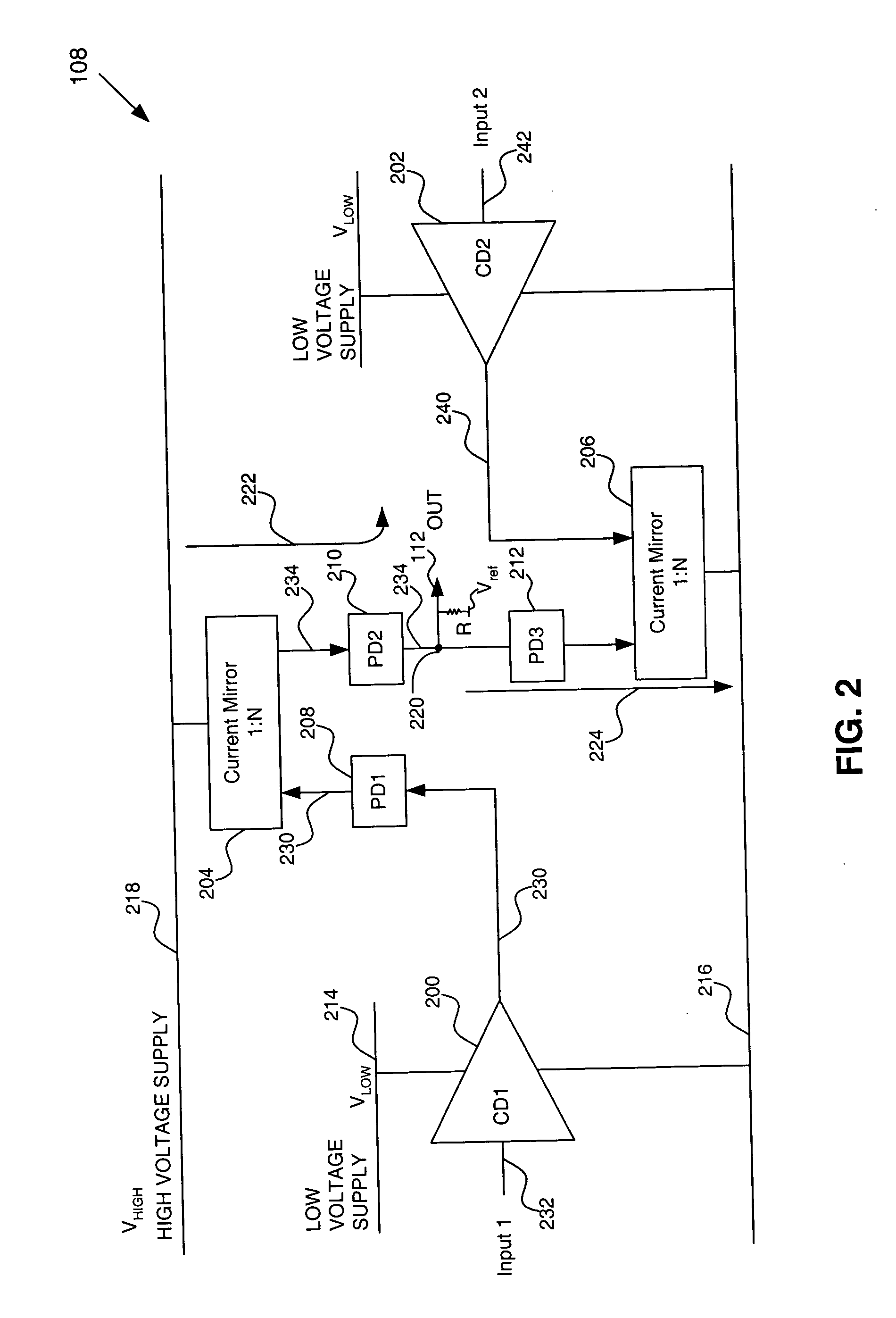
[0018] Embodiments of the present invention provide a signal driving system powered by a first power supply (e.g., about 1.2 Volts), powering first and second drivers, and a second power supply (e.g., about 3.3 Volts), powering a first current mirror. The second power supply produces a supply voltage at a level above a rating of the devices in the signal driving system. Therefore, protection devices are used to protect the elements of the signal driving system from the second power supply. Accordingly, through use of...


PUM


Abstract

A signal driving system generates an output swinging between a first power supply (e.g., about 1.2 Volts), powering first and second drivers, and a second power supply (e.g., about 3.3 Volts), powering a first current mirror. The second power supply is generated external to the signal driving system and is used to allow for a desired common-mode differential output signal range. However, the second power supply produces voltage at a level above a rating of the devices in the signal driving system. Therefore, protection devices are used to protect the elements of the signal driving system from the second power supply. Accordingly, through use of the signal driving system of the present invention, a high voltage current mode driver can operate in a low voltage process without damaging the devices in the signal driving system.

Description

BACKGROUND OF THE INVENTION [0001] 1. Field of the Invention [0002] The present invention is related to signal drivers. [0003] 2. Background Art [0004] Signal driving systems on chips can be used to drive a signal (e.g., a current) through an internal or external termination (e.g., an impedance) in order to create a single-ended or differential output signal (e.g., a single-ended or differential voltage). Typically, a process is rated for a certain maximum supply voltage. Usually, a supply voltage is chosen that is smaller than a maximum allowed process voltage of the signal driving system (e.g., maximum breakdown voltage of devices in the signal driving system). However, some applications specifications for the signal driving system require the signal driving system to operate from a supply voltage that may be higher than the process rated voltage. For example, producing a differential output signal with a signal driving system may not possible when the maximum supply voltage is eq...

Claims


Application Information

Patent Timeline
IPC IPC(8): H02H9/04H03K19/0185
CPCH03K19/018528H02H9/04
Inventor ENGELEN, JOSEPHUS A.E.P. VANCHEUNG, YEE LINGCHAMBERS, MARK J.CHEUNG, DARWIN
Owner AVAGO TECH WIRELESS IP SINGAPORE PTE
Why Eureka
Try Eureka