Method for realizing optical anti-shake of camera module

A camera module and optical anti-shake technology, which is applied in the field of image sensors, can solve problems affecting system stability, easily damaged springs, overshoot, etc., and achieve the effect of optical anti-shake

Inactive Publication Date: 2020-01-07
GALAXYCORE SHANGHAI
View PDF10 Cites 8 Cited by
  • Summary
  • Abstract
  • Description
  • Claims
  • Application Information

AI Technical Summary

Problems solved by technology

In this solution, the moving part of the lens is limited by the upper and lower springs. The selection of the spring determines the displacement. The lower the k value of the spring, the faster the lens moves, but it may overshoot, and the spring is more easily damaged. A higher k value requires a larger current to generate more force to push the lens. In addition, the change of spring k value caused by process deviation will affect the stability of the system.

Method used


Image

  • Method for realizing optical anti-shake of camera module
  • Method for realizing optical anti-shake of camera module

Examples


Embodiment Construction

[0020] In the following detailed description of the preferred embodiment, reference is made to the accompanying drawings which form a part hereof. The accompanying drawings show, by way of example, specific embodiments in which the invention can be practiced. The illustrated embodiments are not intended to be exhaustive of all embodiments in accordance with the invention. It is to be understood that other embodiments may be utilized and structural or logical changes may be made without departing from the scope of the present invention. Accordingly, the following detailed description is not limiting, and the scope of the invention is defined by the appended claims.

[0021] The specific implementation manner of the camera module optical anti-shake of the present invention will be described below with reference to the accompanying drawings.

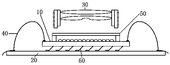
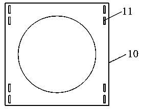
[0022] refer to figure 1 As shown, in the present invention, the camera module includes: an image sensor chip 10 as a mover, a support ...


PUM


Abstract

The invention provides an optical anti-shake implementation method of a camera module. The camera module comprises a lens module, an image sensor chip serving as a rotor and a supporting part servingas a stator. The bonding pad of the image sensor chip is electrically connected to the bonding pad of the support part through a plurality of suspension structures. The suspension structure plays a role in supporting the image sensor chip in a suspended manner and electrically connecting the image sensor chip.

Description

technical field [0001] The invention relates to the technical field of image sensors, in particular to a method for realizing optical anti-shake of a camera module. Background technique [0002] OIS (Optical Image Stabilization) uses the floating lens of the lens to correct the "optical axis offset". The compensated displacement is then compensated by the compensation lens group according to the shake direction and displacement of the lens, so as to effectively overcome the image blur caused by the vibration of the camera. This anti-shake technology has relatively high requirements for lens design and manufacture, and the cost is relatively high. [0003] Traditional smartphones usually achieve anti-shake by adjusting the lens, and adopt a VCM (Voice Coil Motor) structure. The main principle is to control the pull of the spring by changing the DC current of the inner coil of the voice coil motor in a permanent magnetic field. Extended position, so as to drive up and down m...

Claims


Application Information

Patent Timeline
Patent Type & Authority Applications(China)
IPC IPC(8): H04N5/232
CPCH04N23/685
Inventor 赵立新蒋珂玮
Owner GALAXYCORE SHANGHAI
Why Eureka
Try Eureka