Surgical stapler staple-cabin assembly with mounting security safety unit

A safety insurance and stapler technology, which is applied to surgical fixation nails and other directions, can solve the problems of increasing patient medical costs, low reliability, and increasing production costs, and achieves the effects of reducing medical burden, ensuring surgical safety, and reducing processing costs.

Pending Publication Date: 2020-01-10
VICTOR MEDICAL INSTR
View PDF0 Cites 1 Cited by
  • Summary
  • Abstract
  • Description
  • Claims
  • Application Information

AI Technical Summary

Problems solved by technology

[0003] At present, the laparoscopic cutting staplers used in the market are complicated to install safety devices, have many parts, and have low reliability.
At the same time, due to the installation of multiple complex parts, the production cost is increased, and the medical cost of the patient is increased, which is not conducive to the wide-scale popularization and use of surgical instruments.

Method used


Image

  • Surgical stapler staple-cabin assembly with mounting security safety unit
  • Surgical stapler staple-cabin assembly with mounting security safety unit
  • Surgical stapler staple-cabin assembly with mounting security safety unit

Examples


Embodiment Construction

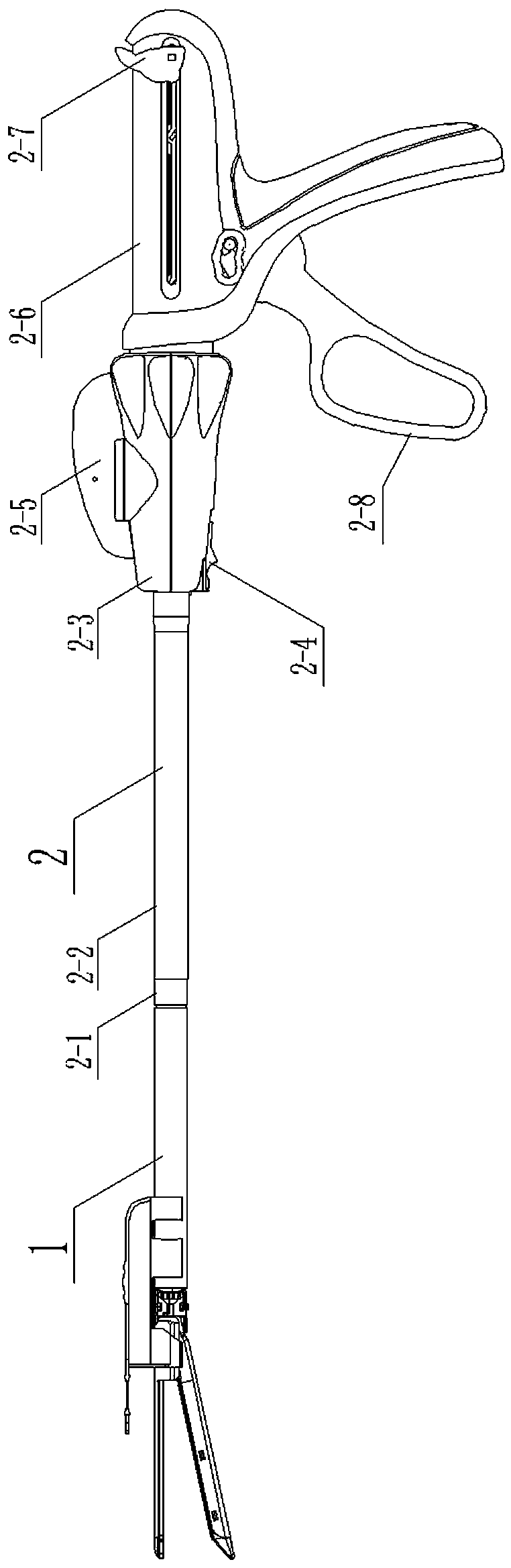
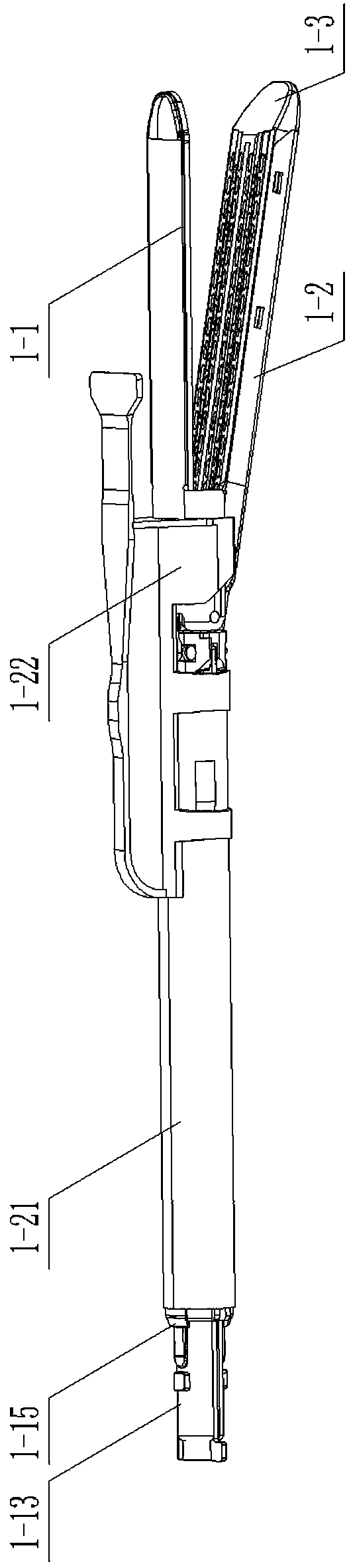
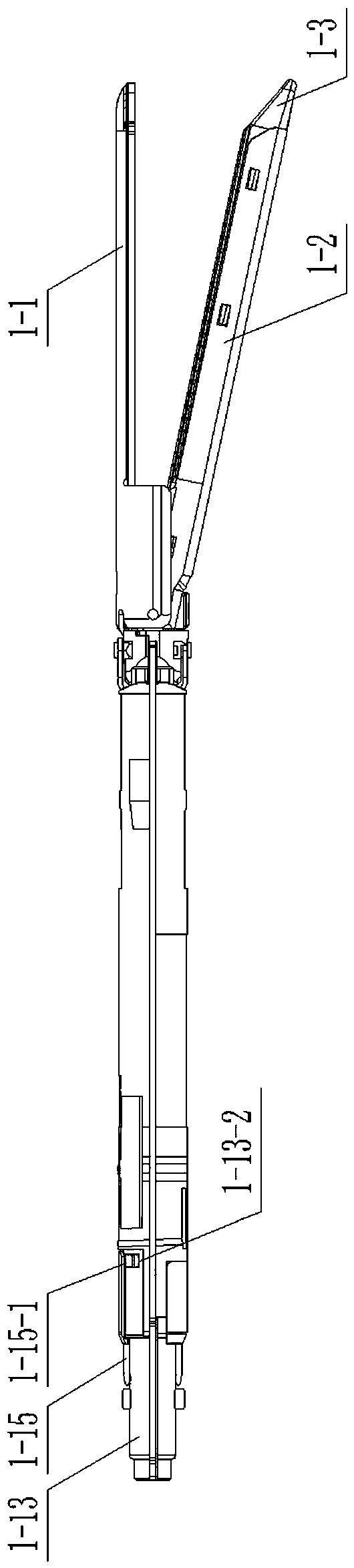
[0088] A staple cartridge assembly for a surgical stapler with a safety device installed includes a nail abutment seat 1-1, a staple cartridge seat 1-2, a staple cartridge 1-3, a push piece 1-4, a titanium nail 1-5, and a push block 1 -6, staple cartridge spring 1-7, lower adapter 1-8, upper adapter 1-9, rotating head pin 1-10, staple cartridge seat pin 1-11, connecting piece 1-12, upper half shell 1-13, lower half shell 1-14, arc buckle 1-15, anti-expansion plate 1-16, H-shaped block 1-17, cutting knife 1-18, driving sleeve 1-19, steering hook 1- 20. Sleeve 1-21 and protective cover 1-22.

[0089] There are six rows of several staple guide grooves 1-1-1 on the above-mentioned nail abutment seat 1-1, a cutting groove 1-1-2 in the middle, a protective cover positioning hole 1-1-3 at the end, and a Locate connection holes 1-1-4.

[0090] The staple cartridge seat 1-2 has a U-shaped structure as a whole, with a knife feed slot 1-2-1 in the middle, two positioning holes 1-2-2 at...


PUM


Abstract

The invention relates to a surgical stapler staple-cabin assembly with a mounting security safety unit. The surgical stapler staple-cabin assembly is a surgical stapler supporting device for applyinga linear-row stapler to intra-cavity tissue and meanwhile cutting the tissue within the linear-row stapler, and is used for avoiding the situation that a staple cabin assembly is not assembled well and accordingly cannot be in use. The surgical stapler staple-cabin assembly includes a staple abutting base, a staple cabin base, rotary head pins, an upper rotary joint, a lower rotary joint, staple cabin spring pieces, a staple cabin, a push block, push pieces, suture staples, staple cabin base pins, an upper half shell, a lower half shell, H-shaped blocks, rising prevention plates, an arc clamp,a cutter, a drive sleeve, a sleeve pipe, a steering pull hook and a protection cover. A limit block is arranged at the inner side of the arc clamp, two clamp pins are arranged at the tail end of thearc clamp, and a fixing point is arranged at the tail end of each clamp pin. A cutter guide groove is formed in the middle of the lower half shell, an arc clamp guide hole is formed in the middle-backportion of the lower half shell, two guide fixing blocks are arranged at the tail end of the lower half shell, two limit pits are formed in front of the guide fixing blocks respectively, and a limitopening is formed in the tail end of a cutter assembly.

Description

technical field [0001] The present invention relates to a surgical stapler staple cartridge assembly with a safety safety device installed, which is a surgical stapler matching device that applies linear rows on intracavity tissue and cuts tissues between the linear row staplers at the same time. It is used to avoid the situation that the staple cartridge assembly cannot be used due to improper assembly. Background technique [0002] In the traditional or open procedure, the doctor directly touches the surgical site. Due to the relatively large trauma of the surgical incision, the patient feels great pain and the postoperative recovery is slow. In minimally invasive surgery, the patient is undergoing abdominal or endoscopic surgery, in which the procedure is performed through a small incision on the patient's body or through a narrow cannula inserted into the wound. Minimally invasive surgery has advantages over open surgery due to its reduced patient trauma, shortened pati...

Claims


Application Information

Patent Timeline
IPC IPC(8): A61B17/072
CPCA61B17/07207A61B2017/07271A61B2017/07278A61B2017/07285
Inventor 王伟江世华王海龙倪志甫
Owner VICTOR MEDICAL INSTR
Why Eureka
Try Eureka