Hydraulic full-automatic coupling disassembly machine

A coupling and fully automatic technology, applied in metal processing, metal processing equipment, manufacturing tools, etc., can solve the problems of difficult operation, low work efficiency, and hidden dangers of safety, so as to improve the safety factor of operations and reduce the labor force of employees. Intensity, the effect of avoiding potential safety hazards

Pending Publication Date: 2020-01-10
枣庄矿业(集团)有限责任公司柴里煤矿
View PDF0 Cites 0 Cited by
  • Summary
  • Abstract
  • Description
  • Claims
  • Application Information

AI Technical Summary

Problems solved by technology

[0002] In the prior art, the method used to disassemble the coupling of the motor is to process the claws according to the size first, then weld the claws to the motor coupling, and place a jack between the claws and the coupling At the end, operate the jack to pull out the coupling. This method is l

Method used


Image

  • Hydraulic full-automatic coupling disassembly machine
  • Hydraulic full-automatic coupling disassembly machine
  • Hydraulic full-automatic coupling disassembly machine

Examples


Embodiment Construction

[0023] The principles and features of the present invention are described below in conjunction with the accompanying drawings, and the examples given are only used to explain the present invention, and are not intended to limit the scope of the present invention.

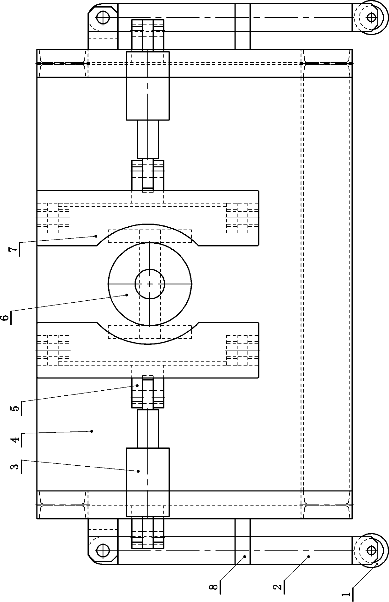
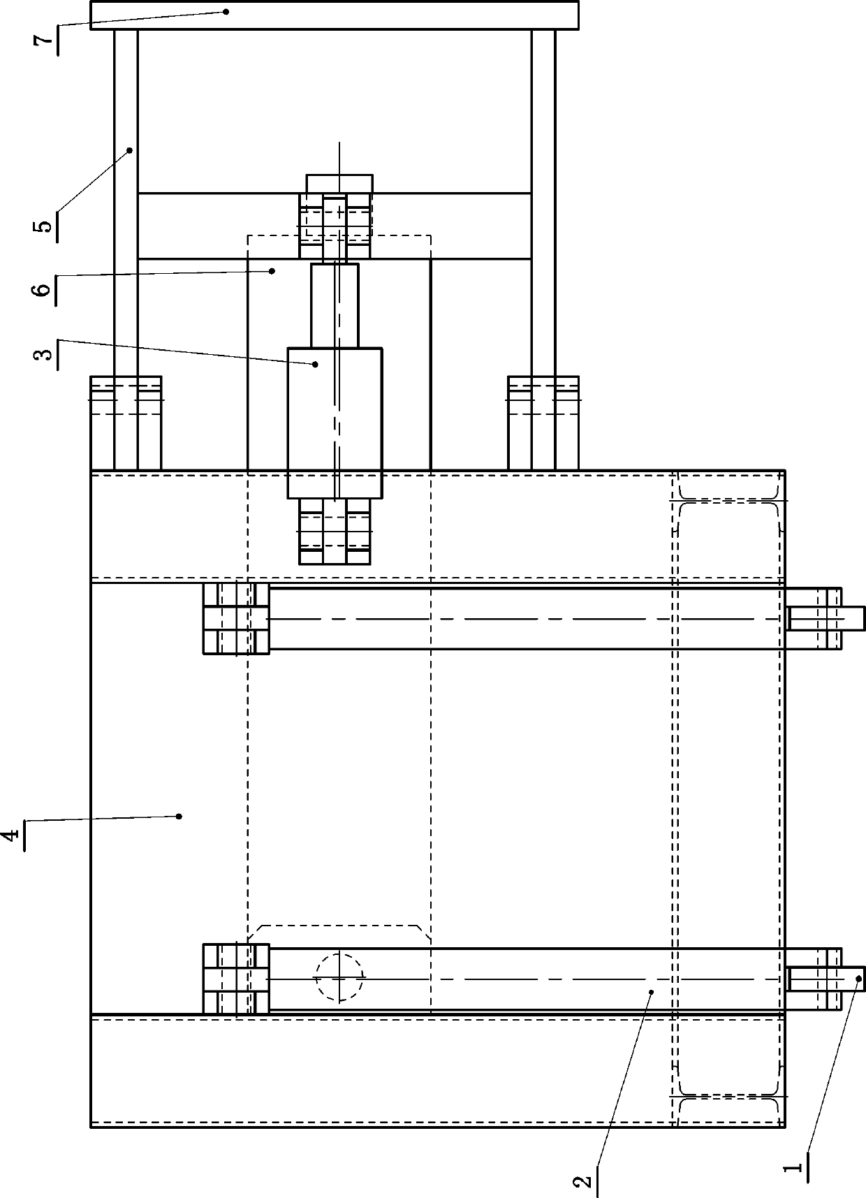
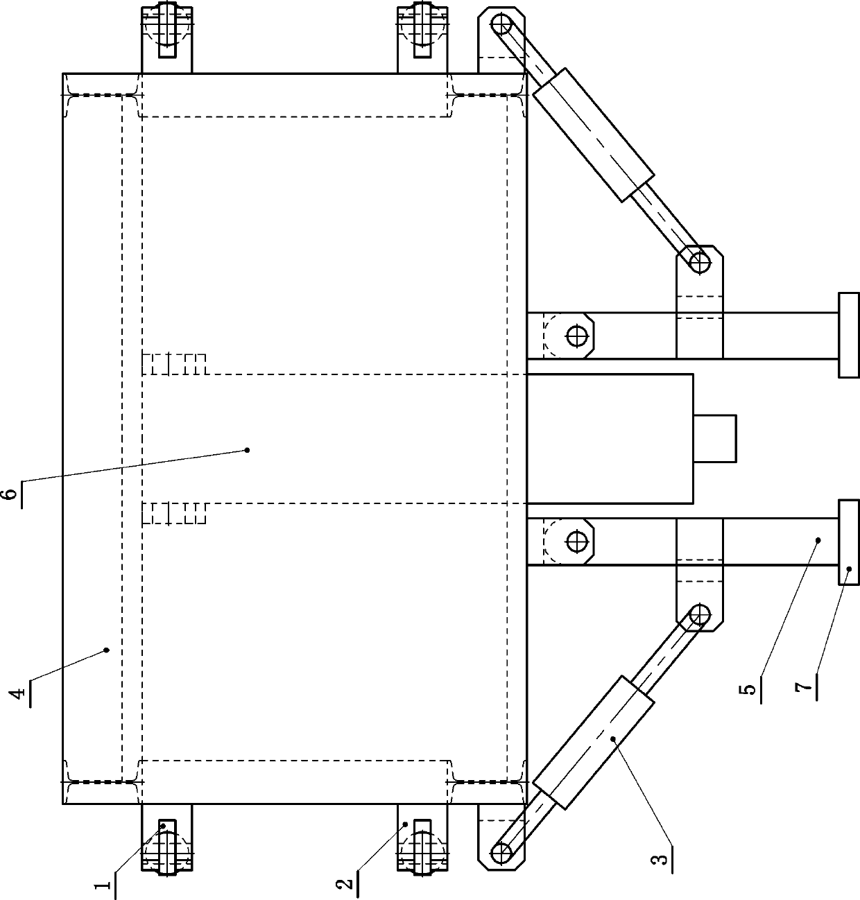
[0024] Such as figure 1 , figure 2 and image 3 As shown, a hydraulic automatic coupling dismantling machine includes a frame body (4), and the left and right sides of the frame body (4) are respectively fixedly connected with vertical support legs (2), and the support legs (2) The frame body (4) is propped up, and the supporting legs (2) are telescopic structures. The lower end of the supporting leg (2) is equipped with a walking wheel (1) for relative rotation, the upper end of the supporting leg (2) is hingedly connected with the frame (4), and the middle or lower part of the supporting leg (2) is positioned by the positioning frame (8) outside the frame (4).

[0025] The front side of the frame body (4) is ...


PUM


Abstract

A hydraulic full-automatic coupling disassembly machine is characterized in that vertically-arranged supporting legs are fixedly connected with the left and right sides of a frame body correspondingly; traveling wheels are mounted at the lower ends of the supporting legs in a relative rotating manner; the upper ends of the supporting legs are hinged with the frame body; the middles or the lower parts of the supporting legs are positioned outside the frame body (4) through positioning frames; mechanical arms which are arranged in a left-right corresponding manner are hinged with the front sideof the frame body; the left and right mechanical arms are arranged corresponding to a motor coupling; a transversely-arranged telescopic jack is fixedly mounted at the middle of the frame body in thefront-rear direction; a telescopic arm of the telescopic jack is positioned between the left and right mechanical arms; holding jacks are hinged with the outer sides of the mechanical arms and transversely arranged; the other ends of the holding jacks are hinged with the frame body; each mechanical arm is of a framework structure and takes the shape of a bracket with a backward opening; two free ends of each mechanical arm are hinged with the frame body in an upper-lower corresponding manner; and the middle or the front part of the transverse section of each mechanical arm is hinged with the corresponding holding jack.

Description

technical field [0001] The invention relates to a mining device, in particular to a hydraulic automatic shaft coupling dismantling machine. Background technique [0002] In the prior art, the method used to disassemble the coupling of the motor is to process the claws according to the size first, then weld the claws to the motor coupling, and place a jack between the claws and the coupling At the end, operate the jack to pull out the coupling. This method is likely to cause uneven force, sagging claws, and low coaxiality, which will increase the resistance of the coupling and easily cause the welding between the claws and the coupling. The seam is torn, so the operation is difficult, the work efficiency is low, and there is a great potential safety hazard. Contents of the invention [0003] The invention aims at the deficiencies, and provides a hydraulic automatic coupling dismantling machine which is safe and reliable in use, convenient in operation and capable of improv...

Claims


Application Information

Patent Timeline
IPC IPC(8): B23P19/027
CPCB23P19/027
Inventor 顾洪利赵新华王冠群季芸帆郑元治付将军王俊平赫章文王涛齐涛刘进水张广奎刘心建
Owner 枣庄矿业(集团)有限责任公司柴里煤矿
Why Eureka
Try Eureka