Tail-end load compensating method dragged by multi-degree-of-freedom cooperation robot

A robot and load force technology, applied in manipulators, program-controlled manipulators, manufacturing tools, etc., can solve the problems of low cost, only the end of the robot can be dragged, and only point drag can be achieved, and the effect of improving lightness can be achieved.

Active Publication Date: 2020-01-10
TIANJIN UNIV
View PDF5 Cites 8 Cited by
  • Summary
  • Abstract
  • Description
  • Claims
  • Application Information

AI Technical Summary

Problems solved by technology

There are three main types of guidance teaching at present. One is the guidance teaching based on the installation of multi-dimensional force / torque sensors at the end of the robot, which is expensive and can only drag the end of the robot; the other is based on joint sensors (torque sensors or dual encoders). Although it can drag the joints, the joint structure is complicated and the cost is increased due to the presence of joint sensors; the third is the sensorless guided teaching based on joint torque compensation and zero-force control, which has the lowest cost, and this method is both It can be dragged by point or track, and has strong adaptability and can be applied to various occasions
[0003] The drag teaching function has become the standard configuration of collaborative robots. However, most collaborative robots on the market are laborious to drag and can only achieve point-to-point dragging.
For collaborative robots without external torque sensors, although dynamic torque compensation can be used to realize direct drag teaching, the incomplete and inaccurate dynamic model makes the effect of zero-force control poor, which affects the dragging effect. flexibility, only point-to-point dragging can be achieved, and it is difficult to achieve track dragging

Method used


Image

  • Tail-end load compensating method dragged by multi-degree-of-freedom cooperation robot
  • Tail-end load compensating method dragged by multi-degree-of-freedom cooperation robot
  • Tail-end load compensating method dragged by multi-degree-of-freedom cooperation robot

Examples


Embodiment Construction

[0033] The technical solutions in the implementation cases of the present invention will be clearly and completely described below with reference to the implementation cases of the present invention. Obviously, the described embodiments are only a part of the embodiments of the present invention, rather than all the embodiments. Based on the embodiments of the present invention, all other embodiments obtained by those of ordinary skill in the art without creative work fall within the protection scope of the present invention.

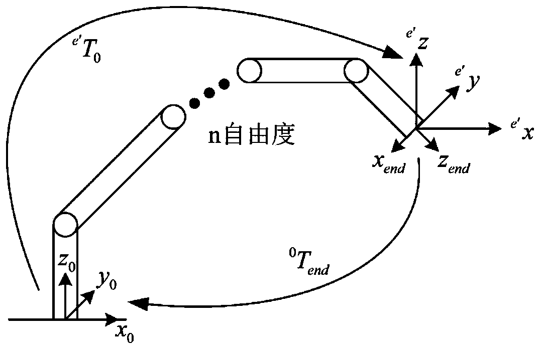
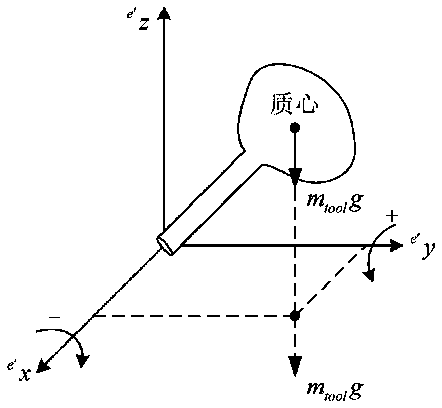
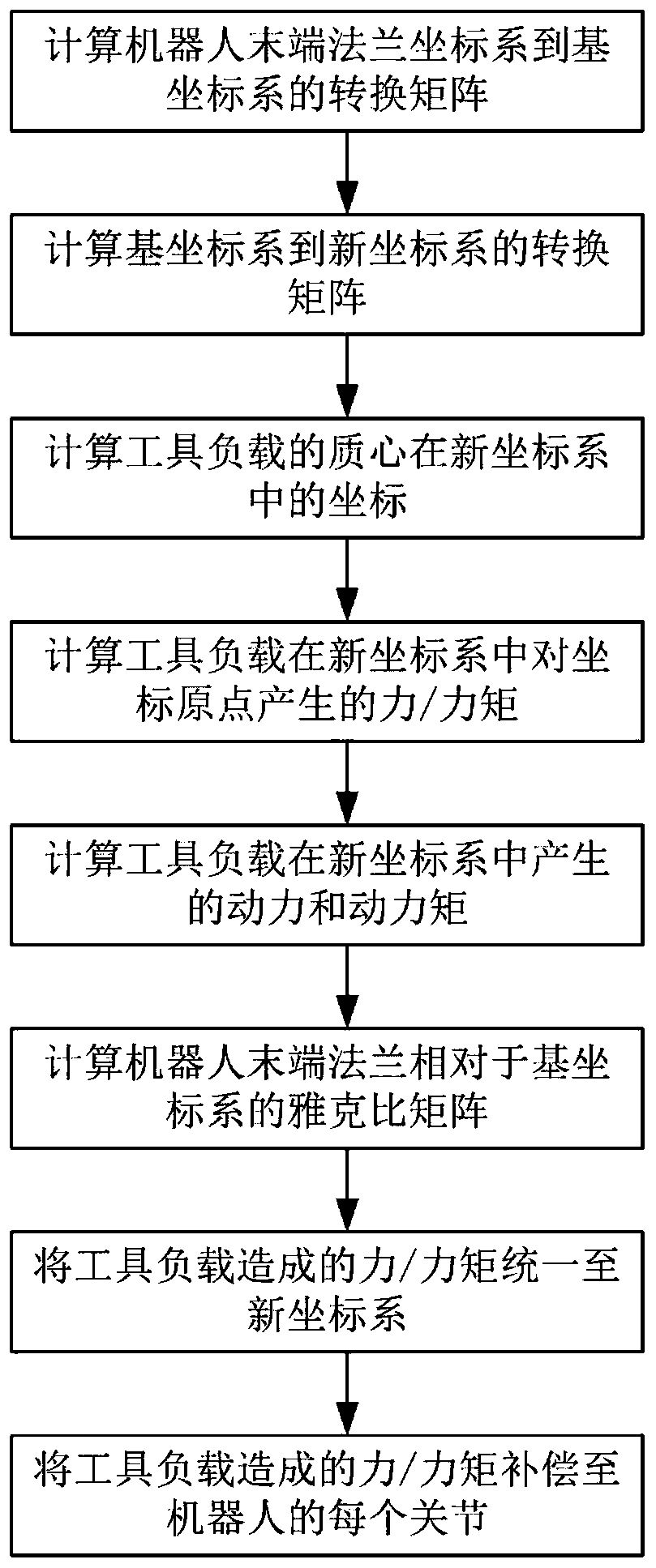
[0034] The present invention provides a method for compensating load force / torque of a robot end tool, comprising the following steps:

[0035] Step S1, corresponding to the process image 3 , to establish the mathematical model of the force and moment of the robot end flange, the model is as follows:

[0036]

[0037] In the formula, F end and T end The external force on the flange of the robot end, including the static force F generated by the t...


PUM


Abstract

The invention discloses a tail-end load compensating method dragged by a multi-degree-of-freedom cooperation robot. The method comprises the steps of 1, building a robot tail-end flange stress and torque mathematic model; 2, building a joint coordinate system, a base coordinate system, a tail end flange coordinate system of the robot and calculating transition matrixes for transition among the coordinate systems; 3, measuring load mass center parameters; 4, building a new coordinate system and calculating static force and static torque generated by a tool loaded at the original point of the new system; 5, calculating dynamic force and dynamic torque generated by the tool loaded at the original point of the new system; 6, calculating a Jacobian matrix of the robot tail-end coordinate systemrelative to the base coordinate system; 7, compensating for torque and force caused by the load of the tool to each joint of the robot. By compensating for force and torque generated by the load, therobot with the load is dragged more portably, and no extra force or torque sensor needs to be added.

Description

technical field [0001] The invention relates to a collaborative robot, in particular to a drag teaching method for a collaborative robot with tools and loads. Background technique [0002] With the application of industrial robots in the fields of grinding, polishing, spraying, gluing, welding, etc., the cooperative control technology of robots is developing in the direction of flexibility, compliance, safety and efficiency. In order to realize the collaborative work of human-machine integration, new requirements are also put forward for robot teaching technology. Compared with the traditional teach pendant teaching technology, the direct drag teaching technology has the advantages of softness and flexibility, and has low requirements on the operator, so it has become the key direction of the development of teaching technology. At present, there are three main types of guided teaching. One is based on the installation of multi-dimensional force / torque sensors at the end of ...

Claims


Application Information

Patent Timeline
Patent Type & Authority Applications(China)
IPC IPC(8): B25J9/16
CPCB25J9/1633B25J9/1607
Inventor 肖聚亮曾帆王铭礼王云鹏赵炜匡加伦
Owner TIANJIN UNIV
Why Eureka
Try Eureka