Supercharge Your Innovation With Domain-Expert AI Agents!

Multifunctional anti-loosening skid

An anti-loosening, multi-functional technology, applied in the direction of transportation, packaging, conveyors, etc., can solve the problems of scratching products, increasing production costs, and easy loosening of product transportation, so as to achieve the effect of preventing scratches and improving stability

Pending Publication Date: 2020-01-10
湖北方鼎科技发展有限公司
View PDF0 Cites 0 Cited by
  • Summary
  • Abstract
  • Description
  • Claims
  • Application Information

AI Technical Summary

Problems solved by technology

[0002] In the manufacturing process of automobiles, it is often necessary to use skids to load products, but the existing skids lack a corresponding binding mechanism when loading products, and the products are prone to loosening during transportation
In order to solve the above problems, the product is generally fixed by manual binding of iron wire, but this method not only wastes time and wastes the iron wire, but also the iron wire will scratch the product, which increases the production cost and reduces the production efficiency

Method used


Image

  • Multifunctional anti-loosening skid
  • Multifunctional anti-loosening skid
  • Multifunctional anti-loosening skid

Examples


Embodiment 1

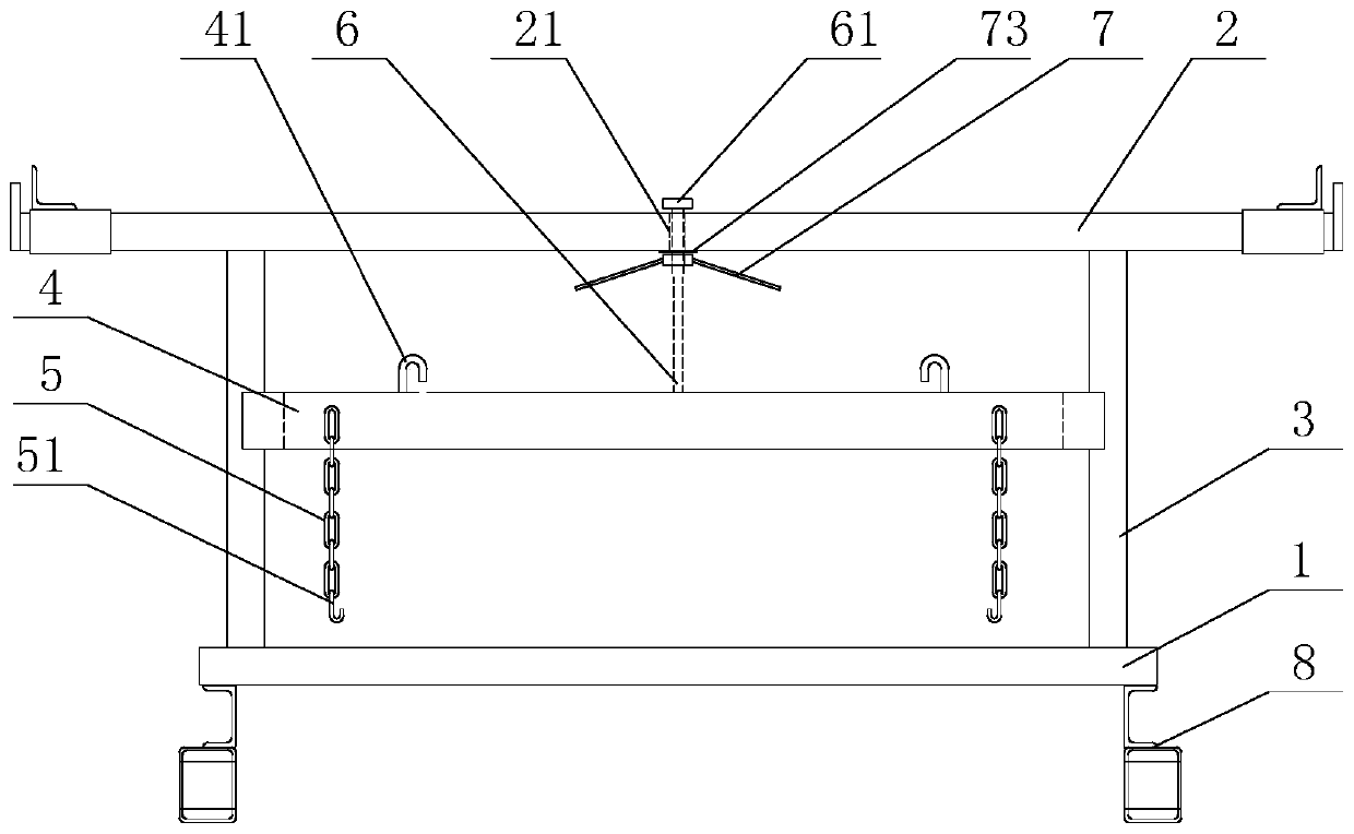
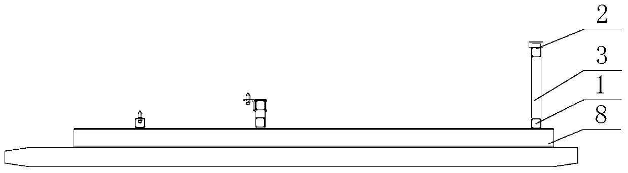
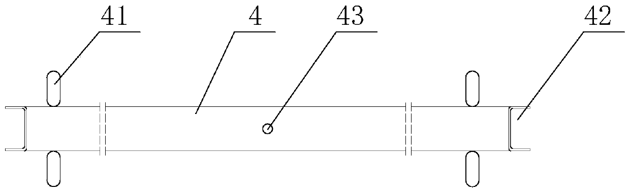
[0041] see figure 1 and figure 2 As shown, the embodiment of the present invention provides a multifunctional anti-loosening skid, including a base 8, and one end of the base 8 is provided with a support frame, and the support frame includes a lower beam 2 connected to the base 8, and the two ends of the lower beam 2 They are respectively connected to the upper beam 1 used to support the product through the column 3; the support frame also includes a lifting rod 4, a screw rod 6 and a rotation adjustment mechanism 7; see image 3 and Figure 4 As shown, the lifting rod 4 is horizontally arranged between the upper beam 1 and the lower beam 2, and is connected with the upper beam 1 through a screw 6; at least one binding mechanism for fixing the product is provided on the lifting rod 4; in this embodiment, Binding mechanism is provided with two, is arranged on the two ends of elevating rod 4 respectively. The rotation adjustment mechanism 7 is installed on the screw rod 6, a...

Embodiment 2

[0050] see Figure 8As shown, the structure of this embodiment is basically the same as that of Embodiment 1, the difference is that in this embodiment, the upper beam 1 is provided with a second connection hole, and the lifting rod 4 is provided with a second threaded through hole 44; the lower end of the screw rod 6 The upper end of the screw rod 6 is rotatably connected to the second connecting hole through the second threaded through hole 44 and threadedly engaged therewith. Specifically, a limit block 61 is provided at the lower end of the screw rod 6 . It is possible to prevent the screw 6 from coming out of the second threaded through hole 44 . One side of the nut 71 is a resisting surface for resisting the lifting rod 4 , and a gasket 73 is arranged between the resisting surface and the lifting rod 4 .

[0051] see Figure 9 and Figure 10 As shown, the working principle of Embodiment 2 of the present invention is:

[0052] 1. After placing the spreader for the em...


PUM


Abstract

The invention discloses a multifunctional anti-loosening skid, and relates to the field of automobile manufacturing equipment. The multifunctional anti-loosening skid comprises a base, wherein a supporting frame is arranged at one end of the base, the supporting frame comprises a lower beam connected with the base, the two ends of the lower beam are connected with an upper beam used for supportinga product through stand columns correspondingly, the supporting frame further comprises a lifting rod, a screw rod and a rotation adjusting mechanism, the lifting rod is horizontally arranged betweenthe upper beam and the lower beam and is connected with the upper beam through the screw rod, the lifting rod is at least provided with a binding mechanism for fixing the product, and the rotation adjusting mechanism is mounted on the screw rod and is used for driving the screw rod to rotate so as to drive the lifting rod to ascend and descend.

Description

technical field [0001] The invention relates to the field of automobile manufacturing equipment, in particular to a multifunctional anti-loosening skid. Background technique [0002] In the manufacturing process of automobiles, it is often necessary to use skids to load products, but the existing skids lack a corresponding binding mechanism when loading products, and the products are prone to loosening during transportation. In order to solve the above problems, the product is generally fixed by manual binding of iron wire, but this method not only wastes time and wastes the iron wire, but also the iron wire will scratch the product, which increases the production cost and reduces the production efficiency. Contents of the invention [0003] In view of the defects existing in the prior art, the object of the present invention is to provide a multi-functional anti-loosening skid, which can quickly fix and tighten products, and improve production efficiency. [0004] In ord...

Claims


Application Information

Patent Timeline
IPC IPC(8): B65G25/06
CPCB65G25/065
Inventor 李光玉宋有兰
Owner 湖北方鼎科技发展有限公司
Features
  • R&D
  • Intellectual Property
  • Life Sciences
  • Materials
  • Tech Scout
  • Unparalleled Data Quality
  • Higher Quality Content
  • 60% Fewer Hallucinations
Learn More