Automatic shuttle-changing device of sewing machine

A technology of a sewing machine and a rotary drive device, which is applied to the winding of the bobbin in the sewing machine, the components of the sewing machine, the sewing equipment, etc., can solve the problems of the inconvenient replacement of the bobbin, the unstable process of changing the shuttle, and the easy falling out of the lock cylinder. The effect of easy replacement, high reliability and smooth moving process

Active Publication Date: 2020-01-10
BULLMER ELECTROMECHANICAL TECH
View PDF9 Cites 2 Cited by
  • Summary
  • Abstract
  • Description
  • Claims
  • Application Information

AI Technical Summary

Problems solved by technology

There are some problems with the automatic bobbin case replacement device currently used on sewing machines, such as: the shuttle changing process is unstable, and the lock cylinder is easy to fall out; it is inconvenient to replace the bobbin disc, and people need to drill under the table for operation, etc.

Method used


Image

  • Automatic shuttle-changing device of sewing machine
  • Automatic shuttle-changing device of sewing machine
  • Automatic shuttle-changing device of sewing machine

Examples


Embodiment 1

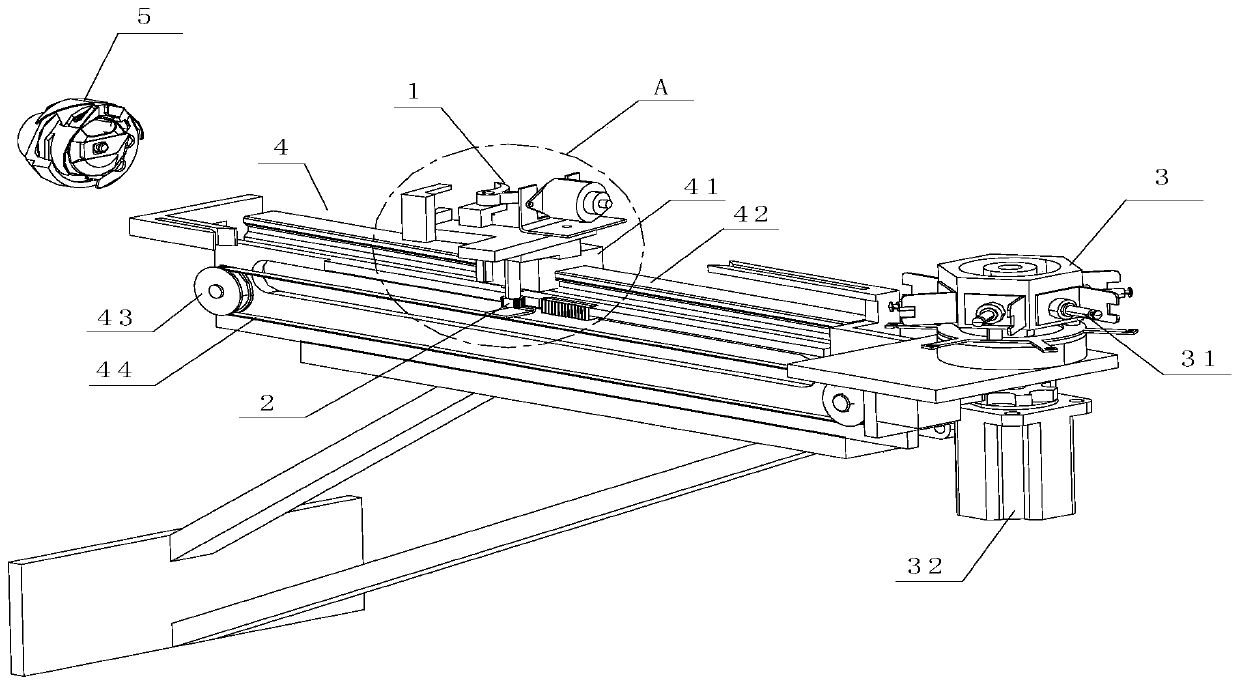
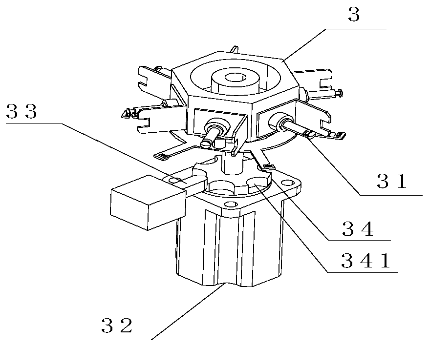
[0068] like Figure 4 and Figure 5 As shown, the automatic shuttle changing device is fixedly installed on the frame 7 through the bracket 71, the bobbin case in the rotary hook 5 and the bobbin case in the storage part 3 are located at the same height, and both are very close to the bottom of the platen 6 surface. In addition, the storage part 3 is also provided with a lifting mechanism 8, and the lifting mechanism 8 includes a lifting guide rail 45 arranged at the front end of the conveying mechanism 4, a lifting slide block 36 arranged on the storage part 3 and fixedly installed on the storage part 3 through a mounting seat 82. The linear drive device 81 below. Wherein, the lifting slide block 36 is installed under the polygonal column through the connecting plate 35 , and is slidably connected with the lifting guide rail 45 . The linear drive device 81 can use devices such as linear motors or cylinders, so that its output shaft is connected to the bottom of the storage...

Embodiment 2

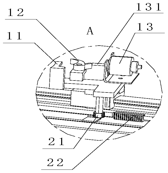
[0070] like Figure 6 and Figure 7 As shown, in the second embodiment, the automatic shuttle changing device is fixedly installed on the frame 7 through the bracket 71, and the height of the bobbin case in the rotary hook 5 is greater than the height of the bobbin case in the storage part 3, that is, the bobbin case in the rotary hook 5 Closer to the lower surface of the platen 6, the storage part 3 is fixed below the conveying mechanism 4 through the bracket 72, so that there is a sufficient distance between the storage part 3 and the platen 6 for the operator to take out the storage part 3. On this basis, the conveying mechanism 4 is also provided with a lifting mechanism 8, and the lifting mechanism 8 drives the conveying mechanism 4 to carry out lifting motion. The rack 22 is fixed between the linear guide rail 42 and the synchronous belt 44 through the connecting rod 23 , and can move up and down simultaneously with the conveying mechanism 4 and remain in the moving str...


PUM


Abstract

The invention provides an automatic shuttle-changing device of a sewing machine; the automatic shuttle-changing device comprises a clamping mechanism for clamping bobbin sleeves, a storage part provided with a plurality of bobbins wound with a bottom thread and the bobbin sleeves, a conveying mechanism for allowing the clamping mechanism to reciprocate between a rotary shuttle and the storage part, and a reversing mechanism for changing the orientation of the clamping mechanism, wherein the reversing mechanism drives the clamping mechanism to rotate around a vertical direction. The automatic shuttle-changing device has the advantages that the reversing mechanism is applied, the clamping mechanism can grab and replace the bobbin sleeves just by horizontally moving and rotating, the moving process is more stable, the bobbins cannot fall out due to too large swinging amplitude of the clamping mechanism, and the reliability is higher.

Description

technical field [0001] The invention relates to the technical field of sewing machines, in particular to an automatic shuttle changing device for sewing machines. Background technique [0002] With the intelligent development of sewing machines, automatic shuttle changing devices have gradually emerged. There are some problems in the automatic bobbin case replacement device used on the sewing machine at present, such as: the shuttle changing process is unstable, and the lock cylinder is easy to fall out; it is inconvenient to change the shuttle disc, and people need to drill under the platen for operation. Contents of the invention [0003] In view of the above-mentioned defects, the purpose of the present invention is to provide a more convenient and reliable sewing machine automatic shuttle changing device. [0004] The invention provides an automatic shuttle changing device for a sewing machine, comprising a clamping mechanism for clamping a bobbin case, a reserve port...

Claims


Application Information

Patent Timeline
IPC IPC(8): D05B59/04
CPCD05B59/04
Inventor 洪武陈建
Owner BULLMER ELECTROMECHANICAL TECH
Why Eureka
Try Eureka