A flue gas heat exchanger

A technology for flue gas heat exchangers and heat exchange fins, which is applied in the direction of heat exchangers, indirect heat exchangers, heat exchanger types, etc., and can solve the problem of dust accumulation on heat exchange fins, affecting heat exchange efficiency, air intake and output Short circulation paths and other issues, to achieve the effect of improving efficiency, increasing heat exchange circulation time, and effectively filtering and collecting

Active Publication Date: 2021-06-18
SICHUAN DESHENG GRP VANADIUM & TITANIUM CO LTD
View PDF0 Cites 0 Cited by
  • Summary
  • Abstract
  • Description
  • Claims
  • Application Information

AI Technical Summary

Problems solved by technology

[0003] Existing flue gas heat exchangers are all heat exchange fin-type heat exchange devices in use. There are two disadvantages in the application of flue gas waste heat recovery. One is that long-term use will Dust accumulation affects the heat exchange efficiency; second, the circulation path of the air intake and outlet is short, and the heat exchange effect is not ideal

Method used


Image

  • A flue gas heat exchanger
  • A flue gas heat exchanger
  • A flue gas heat exchanger

Examples


Embodiment Construction

[0034] In order to make those skilled in the art better understand the technical solution of the invention, the present invention will be further described in detail below with reference to the specific embodiments.

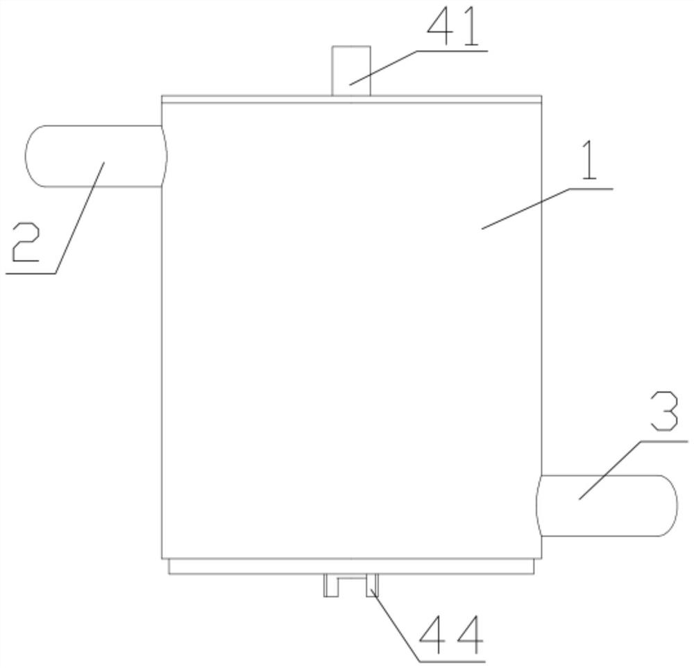
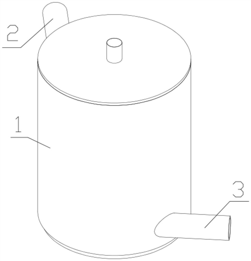
[0035] like Figure 1-8 As shown, the present invention first provides a flue gas heat exchanger, comprising a casing 1, an air inlet 2 and an air outlet 3 on the side of the casing 1, and a heat exchange component 4 in the casing 1;

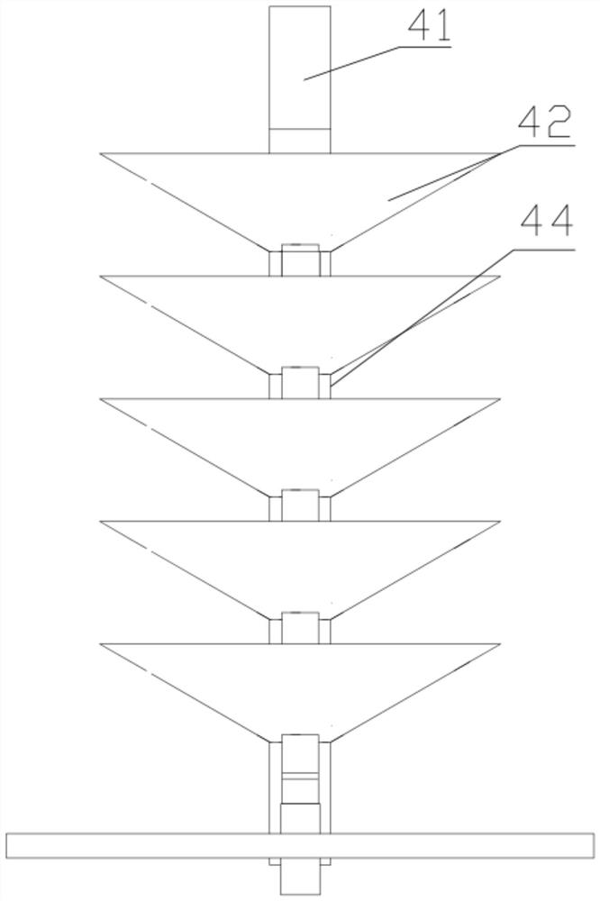
[0036] The heat exchange component 4 includes:

[0037] heat exchange columns 41 penetrating the upper and lower surfaces of the casing 1;

[0038] The heat exchange fins 42 arranged on the heat exchange column 41 in the circumferential direction;

[0039] an air guide fin 43 arranged in an arc shape on the heat exchange fin 42;

[0040] It is arranged on the outside of the heat exchange column 41 and penetrates the air extraction groove 44 of the heat exchange fin 42 from the bottom of the heat exchange fin 42;

[0041] The he...


PUM


Abstract

The invention discloses a flue gas heat exchanger, which comprises a shell, an air inlet and an air outlet on the side of the shell, and a heat exchanging component inside the shell; the heat exchanging component includes: an upper surface penetrating through the shell; The heat exchange column on the lower surface; the heat exchange fin arranged on the heat exchange column in the circumferential direction; the air guide fin arranged on the heat exchange fin in an arc shape; it is arranged outside the heat exchange column and penetrates from the bottom of the heat exchange fin The air extraction groove of the heat exchange fin; the heat exchange material flow path arranged inside the heat exchange column and the heat exchange fin.

Description

technical field [0001] The invention relates to the field of heat exchange equipment, in particular to a flue gas heat exchanger. Background technique [0002] When the flue gas is discharged in the existing iron and steel enterprises, it is often necessary to use a flue gas heat exchanger to recover the waste heat of the flue gas. The waste heat recovery of flue gas mainly converts the heat carried by the flue gas into usable heat through a certain heat exchange method to save fuel. [0003] Existing flue gas heat exchangers use heat exchange fin-type heat exchange devices in use, and there are two drawbacks when applied to flue gas waste heat recovery. One is that long-term use will cause heat exchange fins. Dust accumulation affects the heat exchange efficiency; second, the circulation paths of the intake and exhaust gases are short, and the heat exchange effect is not ideal. SUMMARY OF THE INVENTION [0004] In order to solve the defects existing in the prior art, th...

Claims


Application Information

Patent Timeline
Patent Type & Authority Patents(China)
IPC IPC(8): F28D21/00F28F19/01
CPCF28D21/0003F28F19/01
Inventor 何益先刘德安谢林蒋枢廷陈健康徐瑜
Owner SICHUAN DESHENG GRP VANADIUM & TITANIUM CO LTD
Why Eureka
Try Eureka