
Method for measuring distance between objects by using projections of objects in video

A technology for objects and objects in video, applied in the field of distance measurement, can solve problems such as difficulty in determining the focal plane, system error, and complicated calculation process, and achieve the effect of eliminating calculation errors

Inactive Publication Date: 2020-01-10
章恺熙
View PDF5 Cites 3 Cited by
  • Summary
  • Abstract
  • Description
  • Claims
  • Application Information

AI Technical Summary

Problems solved by technology

[0002] There are currently two main methods for measuring the distance between objects in a video: one is to measure directly on-site, which is the most commonly used method, but if the object to be measured is not there, it cannot be measured; the other is to measure the length of objects on the same focal plane or near the focal plane, According to the scale conversion of the two-dimensional plane coordinate length in the picture, since the lens distortion is a nonlinear change, there is a certain systematic error in this method, and most of the cameras are looking down, so the focal plane is difficult to determine; the third is to measure the shooting location on the spot Multiple sets of three-dimensional coordinate data are associated with the two-dimensional coordinate data in the screen, and the mapping relationship between the two-dimensional coordinates of the screen and the real three-dimensional coordinates is solved by using methods such as affine transformation, thus obtaining the three-dimensional coordinates of each unknown point, using The distance formula calculates the length. Although this method has a wide range of applications, the calculation process is complicated. Due to factors such as lens distortion, the three-dimensional coordinate data measured on the spot must include the measured target

Method used


Image

  • Method for measuring distance between objects by using projections of objects in video
  • Method for measuring distance between objects by using projections of objects in video

Examples


Embodiment Construction

[0013] The present invention will be described in detail below by means of the accompanying drawings.

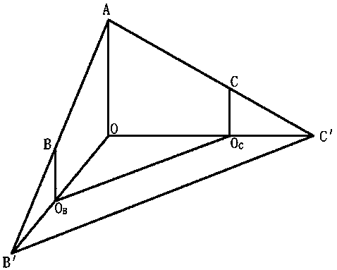
[0014] The method provided by the present invention uses the ground projection point, the relationship between the point to be measured and the three-point line of the camera to construct a tetrahedral model with two faces that are right-angled triangles, such as figure 1 As shown, point A is the vertex of the camera, O is the intersection point of the camera with a bottom surface, B and C are the two measured objects, and the projections of B and C to the ground are O B , O C , Point B' is the projection of point B in the video screen and the ground, point C' is the projection of point C in the video screen and the ground, connect point A to point O with a straight line, and connect point A, point B, point B 'points are connected with a straight line, point A, point C, and point C' are connected with a straight line, and points O, O B Point and B’ are connected by a strai...


PUM


Abstract

The invention provides a method for measuring the distance between objects by using projections of the objects in a video. The method comprises the following steps of S01, building a model, wherein apoint A is set as a vertex of a camera, a point O is set as an intersection point of the bottom surface of the camera, points B and C are set as two measured objects, projections of the points B and Cand the ground are OB and OC respectively, a point B' is the projection of the point B and the ground in a video picture, a point C' is the projection of the point C and the ground in the video picture, the point A is connected with the point O by a straight line, the point A, the point B and the point B' are connected by a straight line, the point A, the point C and the point C' are connected bya straight line, the point O, the point OB and the point B' are connected by a straight line, the point B is connected with the point B' by a straight line, the point B is connected with the point OBby a straight line, the point C is connected with the point OC by a straight line, and the point OB is connected with the point OC by a straight line, so that the model is built; and calculating thedistance between the OB and the OC through mathematical calculation. According to the method, data of two-dimensional coordinates of an original video picture are not used and the calculation error caused by lens distortion is eliminated.

Description

technical field [0001] The invention relates to a method for measuring distance, in particular to a method for measuring distance between objects by using object projection in video. Background technique [0002] There are currently two main methods for measuring the distance between objects in a video: one is to measure directly on-site, which is the most commonly used method, but if the object to be measured is not there, it cannot be measured; the other is to measure the length of objects on the same focal plane or near the focal plane, According to the scale conversion of the two-dimensional plane coordinate length in the picture, since the lens distortion is a nonlinear change, there is a certain systematic error in this method, and most of the cameras are looking down, so the focal plane is difficult to determine; the third is to measure the shooting location on the spot Multiple sets of three-dimensional coordinate data are associated with the two-dimensional coordina...

Claims


Application Information

Patent Timeline
IPC IPC(8): G01B11/14
CPCG01B11/14
Inventor 章恺熙吴昊
Owner 章恺熙
Learn More