Track deformation detection method

A detection method and track technology, applied in measurement devices, instruments, optical devices, etc., can solve problems such as affecting detection accuracy and large errors, and achieve the effects of improving detection accuracy, eliminating calculation errors, and reducing installation work.

Inactive Publication Date: 2020-08-07
SINOHYDRO JIAJIANG HYDRAULIC MACHINERY +1
View PDF7 Cites 3 Cited by
  • Summary
  • Abstract
  • Description
  • Claims
  • Application Information

AI Technical Summary

Problems solved by technology

[0006] The crane track deformation detection device based on the laser rangefinder disclosed in this patent document, in the case of the simultaneous existence of track deformation and wheel d

Method used


Image

  • Track deformation detection method
  • Track deformation detection method
  • Track deformation detection method

Examples


Example Embodiment

[0036] Example 1

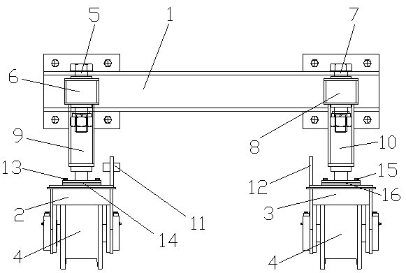
[0037] See figure 1 , A method for detecting track deformation, including the following steps:

[0038] a. Install an encoder on the wheel shaft of the crane, and the encoder updates the measurement data following the movement of the crane. The data signal of the encoder is analyzed through PLC and converted into the crane position value to obtain the track detection position value;

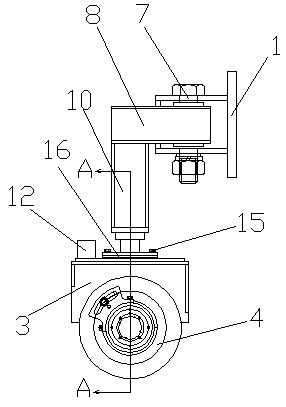
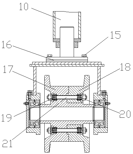
[0039] b. Install and fix the measuring trolley under the walking beam of the crane, the wheel groove of the wheel 4 of the measuring trolley is close to the track and level with the track, and then the laser rangefinder 11 and the reflector 12 are installed on the measuring trolley;

[0040] c. The measuring trolley moves along the full stroke of the crane. The beam of the laser rangefinder 11 extends perpendicular to the track direction and irradiates the reflector 12, the reflector 12 reflects the beam, and the laser rangefinder 11 receives the beam and sends it out between the refle...

Example Embodiment

[0043] Example 2

[0044] See figure 1 , A method for detecting track deformation, including the following steps:

[0045] a. Install an encoder on the wheel shaft of the crane, and the encoder updates the measurement data following the movement of the crane. The data signal of the encoder is analyzed through PLC and converted into the crane position value to obtain the track detection position value;

[0046] b. Install and fix the measuring trolley under the walking beam of the crane, the wheel groove of the wheel 4 of the measuring trolley is close to the track and level with the track, and then the laser rangefinder 11 and the reflector 12 are installed on the measuring trolley;

[0047] c. The measuring trolley moves along the full stroke of the crane. The beam of the laser rangefinder 11 extends perpendicular to the track direction and irradiates the reflector 12, the reflector 12 reflects the beam, and the laser rangefinder 11 receives the beam and sends it out between the refle...

Example Embodiment

[0051] Example 3

[0052] See figure 1 , A method for detecting track deformation, including the following steps:

[0053] a. Install an encoder on the wheel shaft of the crane, and the encoder updates the measurement data following the movement of the crane. The data signal of the encoder is analyzed through PLC and converted into the crane position value to obtain the track detection position value;

[0054] b. Install and fix the measuring trolley under the walking beam of the crane, the wheel groove of the wheel 4 of the measuring trolley is close to the track and level with the track, and then the laser rangefinder 11 and the reflector 12 are installed on the measuring trolley;

[0055] c. The measuring trolley moves along the full stroke of the crane. The beam of the laser rangefinder 11 extends perpendicular to the track direction and irradiates the reflector 12, the reflector 12 reflects the beam, and the laser rangefinder 11 receives the beam and sends it out between the refle...


PUM


Abstract

The invention discloses a rail deformation detection method, which belongs to the technical field of rail detection, and is characterized by comprising the following steps of: a, a data signal of an encoder is analyzed through a PLC, and the data signal is converted into a crane position value; b, the measuring trolley is mounted and fixed below a walking beam of the crane; c, the measuring trolley moves along with the whole stroke of the crane, and the PLC analyzes the data signal of the laser range finder and converts the data signal into a distance value between the laser range finder and the reflector; and d, the PLC compares the distance value between the two tracks with a preset data exception threshold value, and when the distance value exceeds the data exception threshold value, itis judged that the tracks deform. According to the invention, the track position can be detected in real time, the track gauge and position correspondence table is listed in combination with the track gauge data, so that each track gauge point has position traceability, the influence and calculation errors on track gauge detection under the condition of walking wheel deflection can be eliminated,and the detection precision is improved.

Description

Technical field [0001] The invention relates to the technical field of track detection, in particular to a method for detecting track deformation. Background technique [0002] Due to geographical conditions, most large hydropower stations have the characteristics of high dams, large heads, and large capacity of single turbine generators. Hydropower bridge cranes are mainly used for hoisting generator sets and are important equipment for hydropower stations. At present, many large hydropower stations are underground powerhouses, that is, the powerhouses are excavated underground. Affected by geological conditions, the foundation beams of the bridge crane track of underground powerhouses will deform with the rocks. The deformation and displacement of the track beam of the bridge crane in the underground powerhouse of the hydropower station has always troubled hydropower builders and users. [0003] For the deformation of the track foundation caused by the geological and natural en...

Claims


Application Information

Patent Timeline
IPC IPC(8): G01B11/16G01B11/14
CPCG01B11/14G01B11/16
Inventor 张健蒋从军杨芳徐建洪代新启刘建明
Owner SINOHYDRO JIAJIANG HYDRAULIC MACHINERY
Why Eureka
Try Eureka