Motor rotation speed detection system and method and storage medium

A motor speed and detection system technology, applied in linear/angular velocity measurement, speed/acceleration/shock measurement, measurement device, etc., can solve the problems of calculated speed error, inability to detect motor speed, damage to motor mechanical structure and physical characteristics, etc. , to achieve the effect of improving efficiency and accuracy and eliminating calculation errors

Pending Publication Date: 2018-06-29
深圳鳍源科技有限公司
View PDF6 Cites 2 Cited by
  • Summary
  • Abstract
  • Description
  • Claims
  • Application Information

AI Technical Summary

Problems solved by technology

[0004] In the process of realizing the present invention, the inventor found that the prior art has the following defects: the method of detecting the motor speed by relying on the back electromotive force of the phase line depends on other hardware devices such as an oscilloscope, and the motor cannot be detected without an oscilloscope and other equipment. Speed ​​detection; the method of using Hall sensor to detect motor speed needs to install a Hall sensor on a certain position of the motor rotor, thus destroying the original mechanical structure and physical characteristics of the motor, and the calculated speed will introduce errors; grating method It is necessary to fix the disc on the motor shaft, which also destroys the original mechanical structure and physical characteristics of the motor, and the calculated speed will introduce errors

Method used


Image

  • Motor rotation speed detection system and method and storage medium
  • Motor rotation speed detection system and method and storage medium
  • Motor rotation speed detection system and method and storage medium

Examples


Embodiment 1

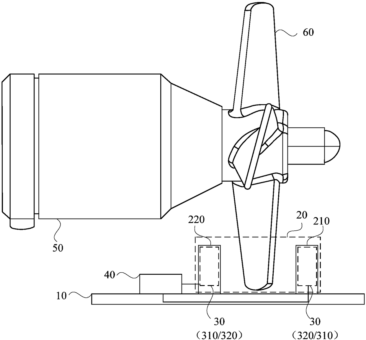
[0023] figure 1 It is a schematic diagram of a motor speed detection system provided by Embodiment 1 of the present invention, as shown in figure 1 As shown, the structure of the motor speed detection system includes:

[0024] The motor installation base plate 10, the concave groove 20 arranged on the motor installation base plate 10, the blockage detection sensor assembly 30 and the controller 40 connected to the blockage detection sensor assembly 30; the concave type groove 20 is used to form the propeller blade 60 of the motor to be tested The rotation channel; the blocking detection sensor assembly 30, which is arranged on the side wall of the concave groove 20, is used to detect the propeller blade 60 passing through the concave groove 20, and sends the detection result to the controller 40; the controller 40 is used for According to the received detection results, the rotational speed of the motor 50 to be tested is calculated.

[0025] Wherein, the motor installation ...

Embodiment 2

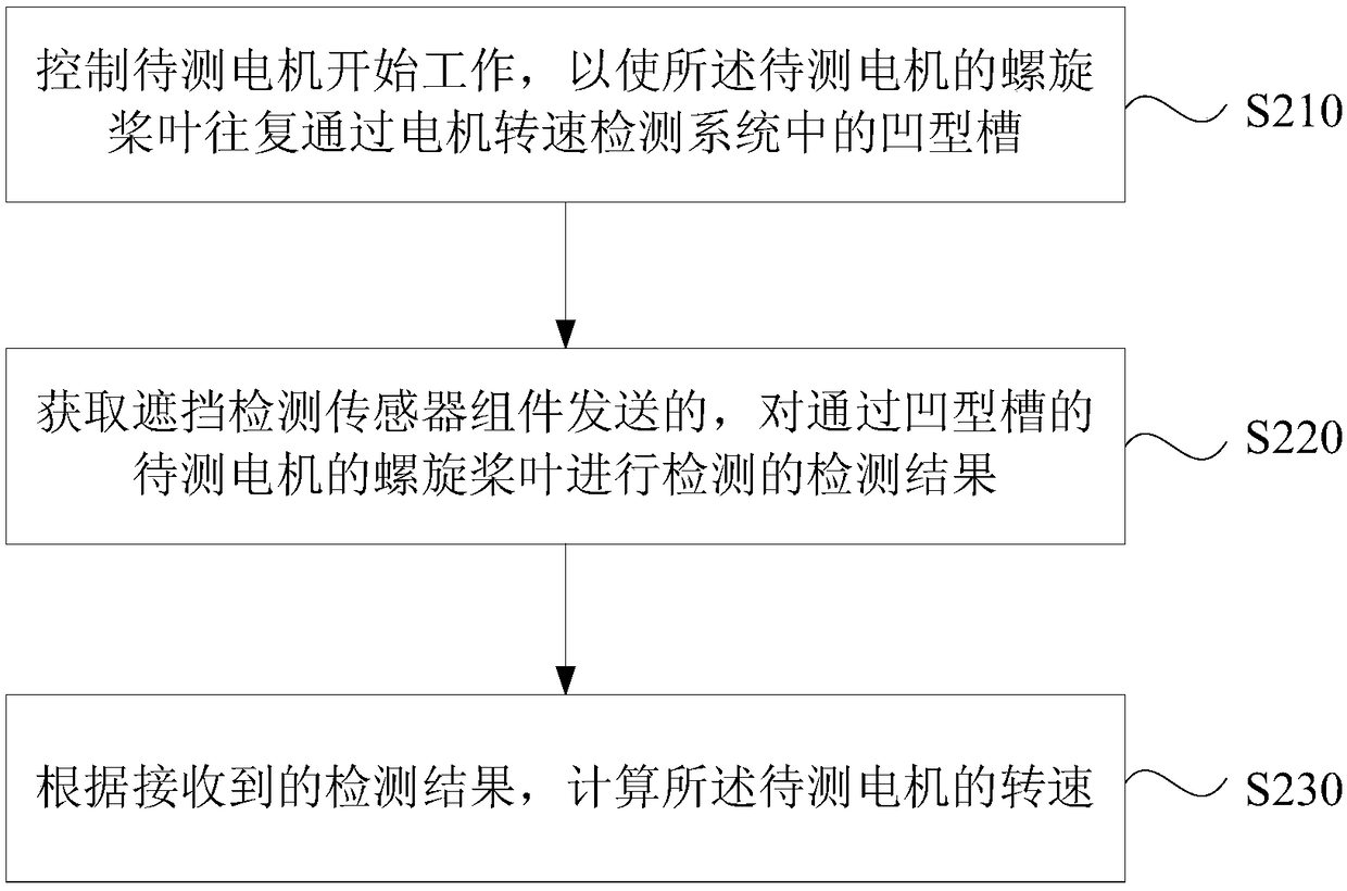
[0036] image 3 It is a flowchart of a motor speed detection method provided in Embodiment 2 of the present invention, which is applicable to the detection of motor speed. The method can be executed by any motor speed detection system described in the embodiment of the present invention. The system can be implemented by software and / or hardware implementations such as image 3 As shown, the method includes the following operations:

[0037] S210. Control the motor to be tested to start working, so that the propeller blade of the motor to be tested reciprocates through the concave groove in the motor speed detection system.

[0038] In the embodiment of the present invention, before detecting the rotational speed of the motor to be tested, the motor to be tested must be controlled to start working so that the propeller blades of the motor to be tested are in a rotating state. The propeller blades of the motor to be tested need to be kept reciprocatingly rotating in the concav...

Embodiment 3

[0050] Figure 4 It is a schematic diagram of a motor speed detection device provided in Embodiment 3 of the present invention, as shown in Figure 4 As shown, the device includes: a motor control module 510, a result acquisition module 520 and a rotational speed calculation module 530, wherein:

[0051] The motor control module 510 is used to control the motor under test to start working, so that the propeller blade of the motor under test reciprocates through the concave groove in the motor speed detection system;

[0052] The result obtaining module 520 is used to obtain the detection result sent by the occlusion detection sensor assembly to detect the propeller blade of the motor to be tested passing through the concave groove;

[0053] The rotational speed calculation module 530 is configured to calculate the rotational speed of the motor under test according to the received detection result.

[0054] In the technical solution of the embodiment of the present invention,...


PUM


Abstract

An embodiment of the invention discloses a motor rotation speed detection system and method and a storage medium. The system comprises a motor mounting base plate, a concave groove arranged on the motor mounting base plate, a blocking detection sensor component and a controller connected with the blocking sensor component, wherein the concave groove is used for forming the rotation channel of thepropeller blades of a to-be-detected motor; the blocking detection sensor component is arranged in the lateral wall of the concave groove and used for detecting the propeller blades passing the concave groove and transmitting the detection result to the controller; the control is used for calculating the rotation speed of the to-be-detected motor according to the received detection result. By thearrangement, the motor rotation speed detection system has the advantages that under the premise that the original mechanical structure and physical properties of the motor are not destroyed and no professional detection equipment is used, motor rotation speed calculation errors are eliminated, and motor rotation speed detection efficiency and accuracy are increased.

Description

technical field [0001] The embodiments of the present invention relate to the technical field of motors, and in particular to a motor speed detection system, method and storage medium. Background technique [0002] With the development of science and technology, the application of motors has been involved in various application fields, such as security monitoring equipment, automatic control equipment and so on. In order to ensure the normal operation of the equipment, it is necessary to detect and control the speed of the motor. [0003] At present, the methods for testing the speed of the motor mainly include the following: (1), relying on the back electromotive force of the phase line to detect the speed of the motor: from the phase line connection to the oscilloscope to observe the voltage signal waveform to calculate the speed. (2) Use Hall sensor: Use its magnetic field-potential conversion relationship to detect the number of pulses to calculate the motor speed. (3)...

Claims


Application Information

Patent Timeline
Patent Type & Authority Applications(China)
IPC IPC(8): G01P3/486
CPCG01P3/486
Inventor 陶冠润
Owner 深圳鳍源科技有限公司
Why Eureka
Try Eureka