
Microphone packaging structure and forming method thereof

A packaging structure and microphone technology, applied in the field of MEMS, can solve the problems of affecting the acoustic performance, increasing the proportion of product failures, reducing the volume of the cavity, etc., to achieve the effect of increasing the contact area and improving the bonding reliability.

Pending Publication Date: 2020-01-10
MEMSENSING MICROSYST SUZHOU CHINA
View PDF0 Cites 0 Cited by
  • Summary
  • Abstract
  • Description
  • Claims
  • Application Information

AI Technical Summary

Problems solved by technology

In the large-scale manufacturing process, due to the uneven dispensing amount of the machine, when the MEMS microphone is pasted on the substrate and squeezed with the colloid, the colloid will often overflow to the inner and outer sides of the side wall of the MEMS microphone. Excessive colloid When part of it overflows into the cavity of the MEMS microphone, it usually causes the cavity of the MEMS microphone to be too small, which affects its acoustic performance and leads to an increase in the failure rate of the product
[0003] In the prior art, the inner side wall of the MEMS microphone cavity is changed from smooth etching to a rough surface, so as to reduce the impact of colloid overflow on the MEMS microphone cavity, but in fact, the effect of this solution is not very ideal, because the MEMS microphone The cavity itself is very small, even if the colloid does not climb up along the side wall, it still exists in the inner space of the cavity, resulting in a smaller cavity volume, which still has a great impact on the acoustic performance

Method used


Image

  • Microphone packaging structure and forming method thereof
  • Microphone packaging structure and forming method thereof
  • Microphone packaging structure and forming method thereof

Examples


Embodiment Construction

[0035] The specific implementation of a microphone package structure and its forming method provided by the present invention will be described in detail below with reference to the accompanying drawings.

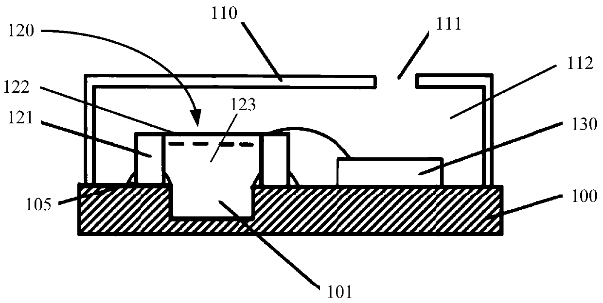
[0036] Please refer to figure 1 , is a structural schematic diagram of a microphone package structure according to a specific embodiment of the present invention.

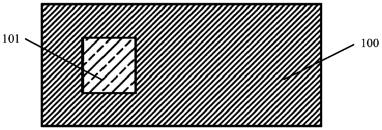
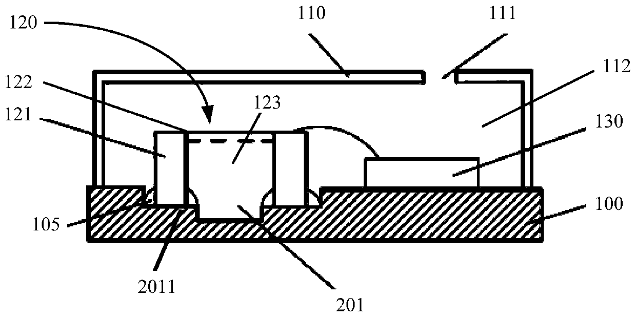
[0037] The microphone packaging structure includes: a substrate 100, a first recess 101 is formed on the surface of the substrate 100; The first cavity 112, the first recess 101 is located in the first cavity 112; the microphone chip 120 is arranged in the first cavity 112, the microphone chip 120 includes a pressure sensing layer 122 and a support structure 121, a second cavity 123 is formed between the support structure 121 and the pressure-sensing layer 122, the top of the support structure 121 supports the pressure-sensing layer 122, and the bottom is fixed on the surface of the substrate 100, so that the ...


PUM


Abstract

The invention relates to a microphone packaging structure and a forming method thereof, and the microphone packaging structure comprises a substrate, and a first concave part is formed on the surfaceof the substrate; a packaging shell which is fixed on the surface of the substrate, and a first cavity is formed between the packaging shell and the substrate; a microphone chip which is arranged in the first cavity, wherein the microphone chip comprises a pressure sensing layer and a supporting structure. And a second cavity is formed between the supporting structure and the pressure sensing layer, the top of the supporting structure supports the pressure sensing layer, and the bottom of the supporting structure is fixed to the surface of the substrate, so that the second cavity communicateswith the first concave part, and the first concave part is located in the projection of the second cavity on the surface of the substrate. The acoustic performance of the microphone chip of the microphone packaging structure is not affected by the packaging process.

Description

technical field [0001] The invention relates to the technical field of MEMS, in particular to a microphone packaging structure and a forming method thereof. Background technique [0002] In the prior art, in the packaging structure of the MEMS microphone, the MEMS microphone is usually solidified and connected to the substrate through glue. In the large-scale manufacturing process, due to the uneven dispensing amount of the machine, when the MEMS microphone is pasted on the substrate and squeezed with the colloid, the colloid will often overflow to the inner and outer sides of the side wall of the MEMS microphone. Excessive colloid When part of it overflows into the cavity of the MEMS microphone, the cavity of the MEMS microphone is usually too small, which affects its acoustic performance and leads to an increase in the failure rate of the product. [0003] In the prior art, the inner side wall of the MEMS microphone cavity is changed from smooth etching to rough surface, ...

Claims


Application Information

Patent Timeline
Patent Type & Authority Applications(China)
IPC IPC(8): H04R19/04H04R1/08
CPCH04R19/04H04R1/08H04R2201/003
Inventor 梅嘉欣张永强唐行明
Owner MEMSENSING MICROSYST SUZHOU CHINA
Learn More