Eureka AIR delivers breakthrough ideas for toughest innovation challenges, trusted by R&D personnel around the world.

Roller massage machine core

A core and roller technology, which is applied in the direction of roller massage, kneading massage equipment, massage auxiliary products, etc., can solve the problems of large volume of massage equipment, large volume of massage core, and obstacles in the placement of massage equipment. Reasonable, achieve the effect of stable movement and directional guarantee

Pending Publication Date: 2020-01-14
SHANGHAI BACKROBO WELLNESS CO LTD
View PDF0 Cites 4 Cited by
  • Summary
  • Abstract
  • Description
  • Claims
  • Application Information

AI Technical Summary

Problems solved by technology

The massage machine core that realizes the above massage methods requires multiple driving devices, and the corresponding massage machine core is also large in size, resulting in an increase in the volume of the massage equipment, and there will be great obstacles to the placement of the massage equipment

Method used


Image

  • Roller massage machine core
  • Roller massage machine core
  • Roller massage machine core

Examples


Embodiment 1

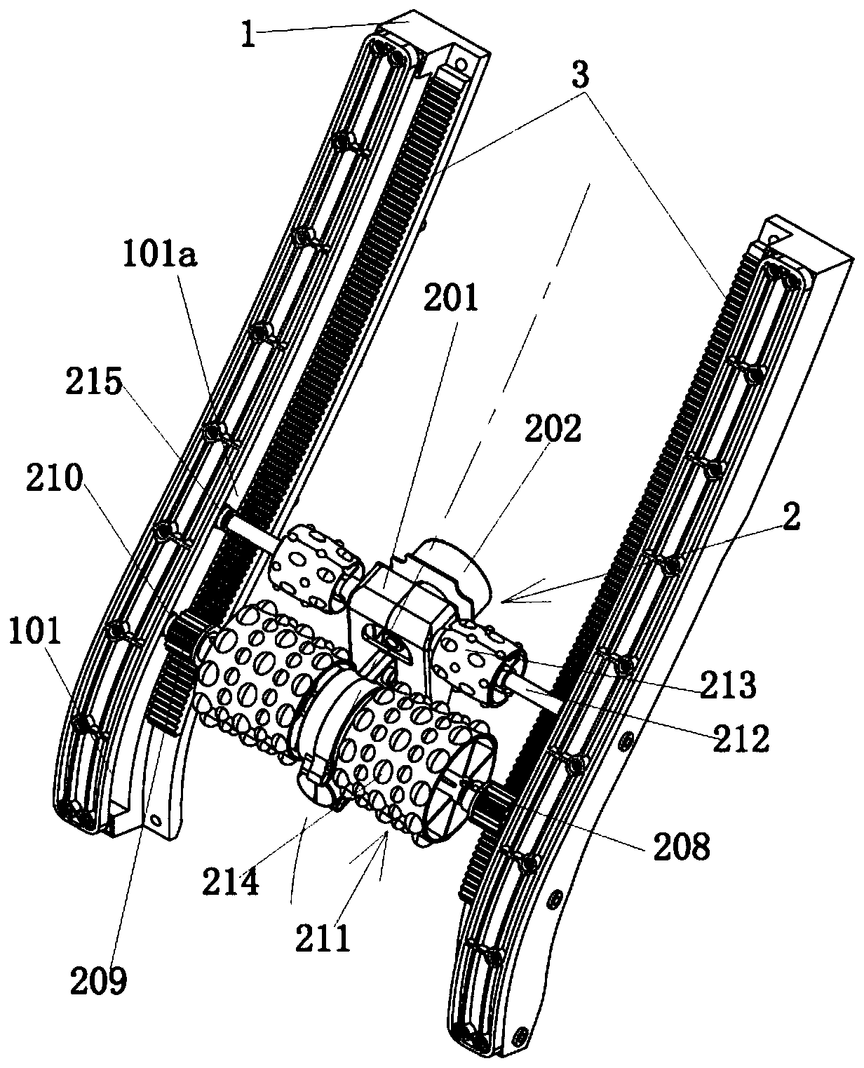
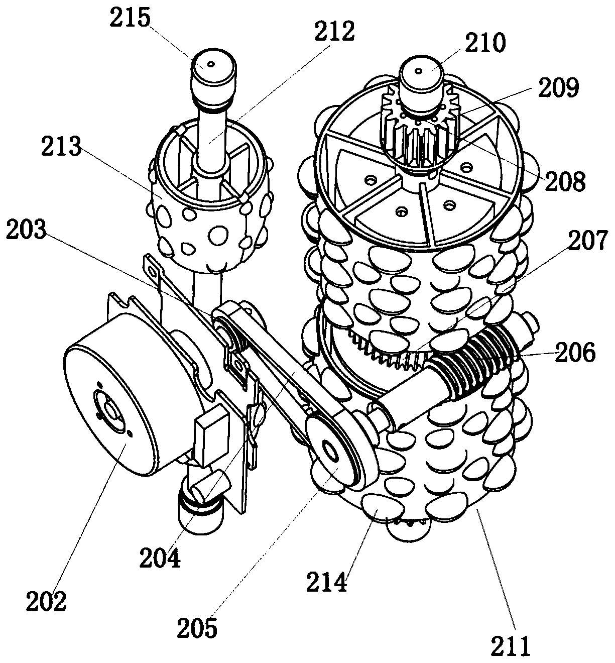
[0028] Such as Figure 1-4 As shown, a roller massage movement is built into the flexible layer of the chair back according to the common knowledge. The movement includes a bracket 1 and a movable massage part 2 arranged on the bracket 1. The guide rail assembly, the movable massage part 2 is arranged between a pair of guide rail assemblies and is movably matched with the pair of guide rail assemblies. Wherein, the shapes of the bracket 1 and the guide rail assembly are similar to the curve of the neck, shoulders and back of the human body, so that the moving track of the movable massage part 2 matches the curve of the neck, shoulders and back of the human body to obtain the best massage experience.

[0029] The above activities Massage Section 2 include:

[0030] Main seat 201;

[0031] A power unit arranged on the main base 201 to drive the main base 201 to move up and down along a pair of guide rail assemblies;

[0032] And at least one massage rolling body that is rotat...

Embodiment 2

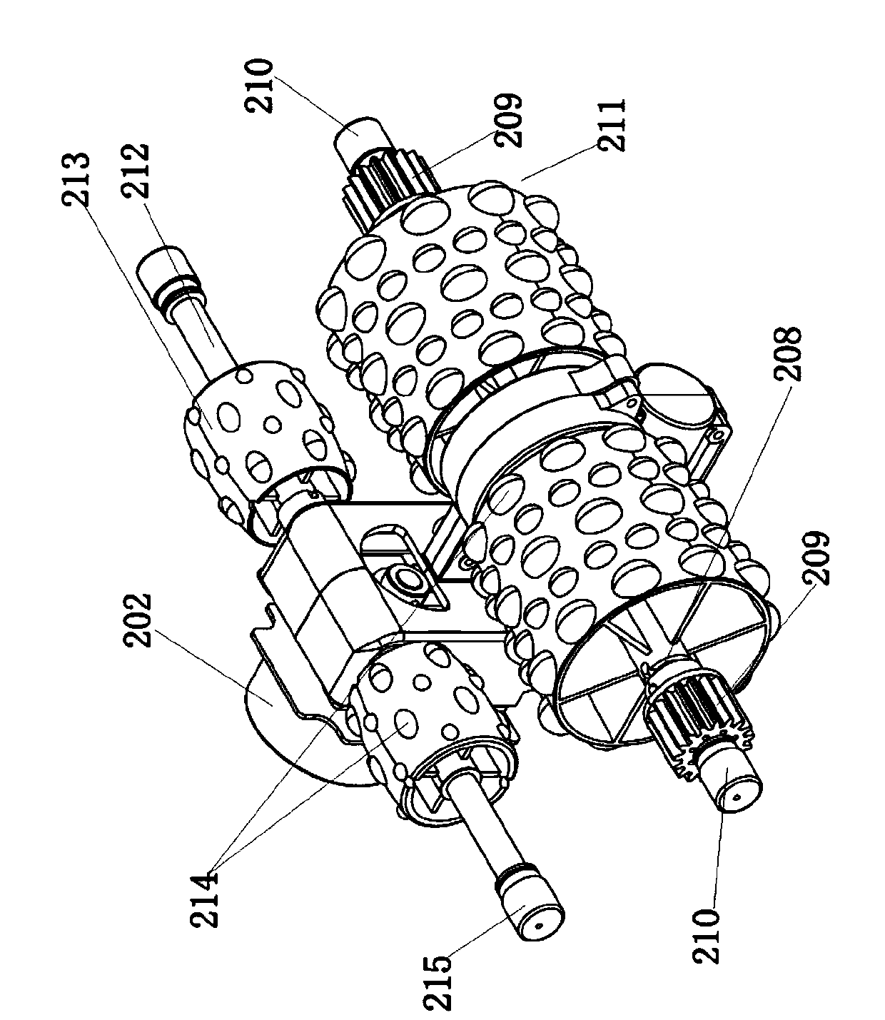
[0044] Such as Figure 5-6 As shown, the difference between Embodiment 2 and Embodiment 1 is that: the driving motor 202 is coaxially installed in the driving rolling body 211, and the driving shaft 208 is set as the output shaft of the driving motor 202, and the driving motor 202 can directly drive the driving rolling body. The body 211 and the driving gear 209 rotate together, and the transmission efficiency is higher.

[0045] Embodiment 1 also has the following common points with embodiment 2:

[0046] The above-mentioned massage protrusions 214 are configured as elastically deformable units made of elastic materials, such as PU materials, so as to improve the comfort of massage.

[0047] The above-mentioned active rolling elements 211 and driven rolling elements 213 are all cylindrical structures, i.e. hollow structures, to reduce weight and reduce the power loss of the power unit; The general width and size are similar, so that all areas of the neck, shoulders and back...


PUM


Abstract

The invention relates to the technical field of massage equipment, in particular to a roller massage machine core which comprises a support and a movable massage part arranged on the support, the support is provided with a pair of guide rail assemblies arranged left and right in a spaced mode, and the movable massage part is located between the pair of guide rail assemblies. The movable massage part comprises a main seat, a power unit arranged on the main seat and driving the main seat to do lifting motion along the pair of guide rail assemblies; and a massage rolling body is rotationally connected to the main seat and rolling on a human body during massage. During massaging, a driving rolling body is driven by the power unit to rotate so as to drive the whole movable massage part to movealong the portion needing to-be-massaged of the human body, a driven rolling body rolls on the portion needing to-be-massaged of the human body, and the massage protrusions on the peripheral walls ofthe driving rolling body and the driven rolling body repeatedly extrude the portion needing to-be-massaged of the human body to achieve the lifting rolling massage function.

Description

technical field [0001] The invention relates to the technical field of massage equipment, in particular to a rolling movement built in the massage equipment. Background technique [0002] Massage equipment has become more and more popular in daily life, and the muscle relaxation function of massage equipment can greatly improve the quality of life of users. For workers who sit and work for more than eight hours a day, the body bears more pressure than others every day (such as neck and shoulders), so it is necessary to relax and massage at regular intervals. At present, many massage devices in the market use traditional massage cores. The massage core is placed on the sliding track of the massage equipment, and the massage function is realized through the sliding and vibration of the massage rollers. The massage core slides up and down on the slide rail to realize the massage function. Massage different parts of the user. Or the massage machine core is placed in a fixed po...

Claims


Application Information

Patent Timeline
Patent Type & Authority Applications(China)
IPC IPC(8): A61H15/00A61H7/00A61H1/00
CPCA61H15/0078A61H7/007A61H1/00A61H2201/0142A61H2201/0149A61H2201/1207A61H2205/04A61H2205/062A61H2015/0021
Inventor 刘文超李勇兵亓飞
Owner SHANGHAI BACKROBO WELLNESS CO LTD
Why Eureka
Eureka Blog
Learn More