Multi-channel activated carbon adsorption device

An activated carbon adsorption and multi-channel technology, which is applied to the separation of dispersed particles, chemical instruments and methods, and separation methods, can solve the problems of fast adsorption attenuation effect, workload cost, and increased maintenance, and achieve consistent adsorption attenuation effect and reduce maintenance. The effect of reasonable cost and structural design

Pending Publication Date: 2020-01-14
SHANDONG GRAD GROUP
View PDF0 Cites 0 Cited by
  • Summary
  • Abstract
  • Description
  • Claims
  • Application Information

AI Technical Summary

Problems solved by technology

[0002] In the activated carbon box used in the prior art, for those with multi-layer activated carbon plates inside, the exhaust gas needs to pass through the activated carbon plates one by one. Since the adsorption principle of activated carbon is to absorb harmful components in the exhaust gas through the fine pores on its surface, the activated carbon located on the front side The content of harmful components in the exhaust gas that the plate contacts is relatively high, so its adsorption attenuation effect is faster, and the corresponding service life is short. The adsorption attenuation effect and service life of the activated carbon plate on the rear side are opposite. In order to ensure the lowest use cost, it is necessary to Activated carbon is replaced at different time points during the service life of the product. Although the use value of activated carbon is guaranteed, it increases the workload and unnecessary costs in maintenance, and ultimately needs to be borne by the user.

Method used


Image

  • Multi-channel activated carbon adsorption device
  • Multi-channel activated carbon adsorption device
  • Multi-channel activated carbon adsorption device

Examples


Embodiment Construction

[0028] The implementation of the present invention will be illustrated by specific specific examples below, and those skilled in the art can easily understand other advantages and effects of the present invention from the contents disclosed in this specification.

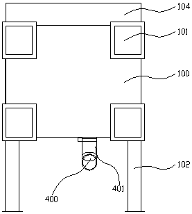
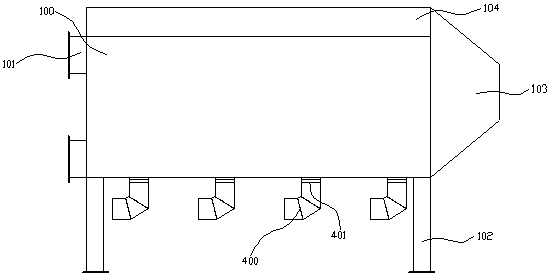
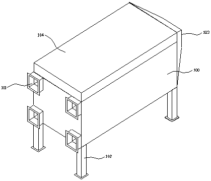
[0029] according to Figure 1 to Figure 6 As shown: this embodiment provides a multi-channel activated carbon adsorption device, including an activated carbon box 100 and four groups of activated carbon plates 300 inside it, wherein:

[0030] The activated carbon box 100 is a cuboid box body as a whole, and four separate adsorption chambers 500 are arranged respectively from the left side to the right side inside the activated carbon box 100. The adsorption chambers 500 are separated by partitions, and the partitions are arranged vertically and their The edge is connected and airtight with the inner wall of the activated carbon box 100, and the middle part of the adsorption chamber 500 is provided with an activated ...


PUM


Abstract

The invention relates to a multi-channel activated carbon adsorption device, comprising an activated carbon box, wherein a plurality of independently arranged adsorption chambers are arranged in the activated carbon box; activated carbon plates are arranged at the middle parts of the adsorption chambers; the activated carbon plates divide the interiors of the adsorption chambers into air inlet chambers and air outlet chambers which are relatively independent; air inlets and air outlets are respectively formed in the outer sides of the activated carbon box; the air inlets and the adsorption chambers are arranged in a one-to-one correspondence manner; the air inlets are communicated with the air inlet chambers corresponding to the adsorption chambers; and the air outlets are respectively communicated with the air outlet chambers. The device is reasonable in structural design; the internal space of the activated carbon box is independently arranged to form the adsorption chambers; meanwhile, the same amount of waste gas is fed into each adsorption chamber, so the adsorption attenuation effect of each activated carbon plate in the use process is consistent, and the maximization of theuse value of the activated carbon is guaranteed; and all the activated carbon plates can be replaced at the same time through one-time maintenance during maintenance, so maintenance cost is reduced.

Description

technical field [0001] The invention relates to the technical field of environmental protection equipment, in particular to a multi-channel activated carbon adsorption device. Background technique [0002] In the activated carbon box used in the prior art, for those with multi-layer activated carbon plates inside, the exhaust gas needs to pass through the activated carbon plates one by one. Since the adsorption principle of activated carbon is to absorb harmful components in the exhaust gas through the fine pores on its surface, the activated carbon located on the front side The content of harmful components in the exhaust gas that the plate contacts is relatively high, so its adsorption attenuation effect is faster, and the corresponding service life is short. The adsorption attenuation effect and service life of the activated carbon plate on the rear side are opposite. In order to ensure the lowest use cost, it is necessary to Activated carbon is replaced at different time...

Claims


Application Information

Patent Timeline
Patent Type & Authority Applications(China)
IPC IPC(8): B01D53/04
CPCB01D53/04
Inventor 张连秀任世聪高洪超王瑞王帅
Owner SHANDONG GRAD GROUP
Why Eureka
Try Eureka