Winding equipment for optical fibers

A kind of equipment and optical fiber technology, which is applied in the field of optical fiber winding equipment, can solve the problems such as poor winding effect of optical fiber, and achieve the effects of avoiding scatter, improving practicability, and facilitating lifting

Pending Publication Date: 2020-01-14
南通光烁通信设备有限公司
View PDF0 Cites 3 Cited by
  • Summary
  • Abstract
  • Description
  • Claims
  • Application Information

AI Technical Summary

Problems solved by technology

[0003] The purpose of the present invention is to provide a winding device for optical fiber, which has the advantage of limiting the position of the wound optical fiber, and solves the problem that the winding effect of the winding device is poor

Method used


Image

  • Winding equipment for optical fibers
  • Winding equipment for optical fibers
  • Winding equipment for optical fibers

Examples


Embodiment Construction

[0019] The following will clearly and completely describe the technical solutions in the embodiments of the present invention with reference to the accompanying drawings in the embodiments of the present invention. Obviously, the described embodiments are only some, not all, embodiments of the present invention. Based on the embodiments of the present invention, all other embodiments obtained by persons of ordinary skill in the art without making creative efforts belong to the protection scope of the present invention.

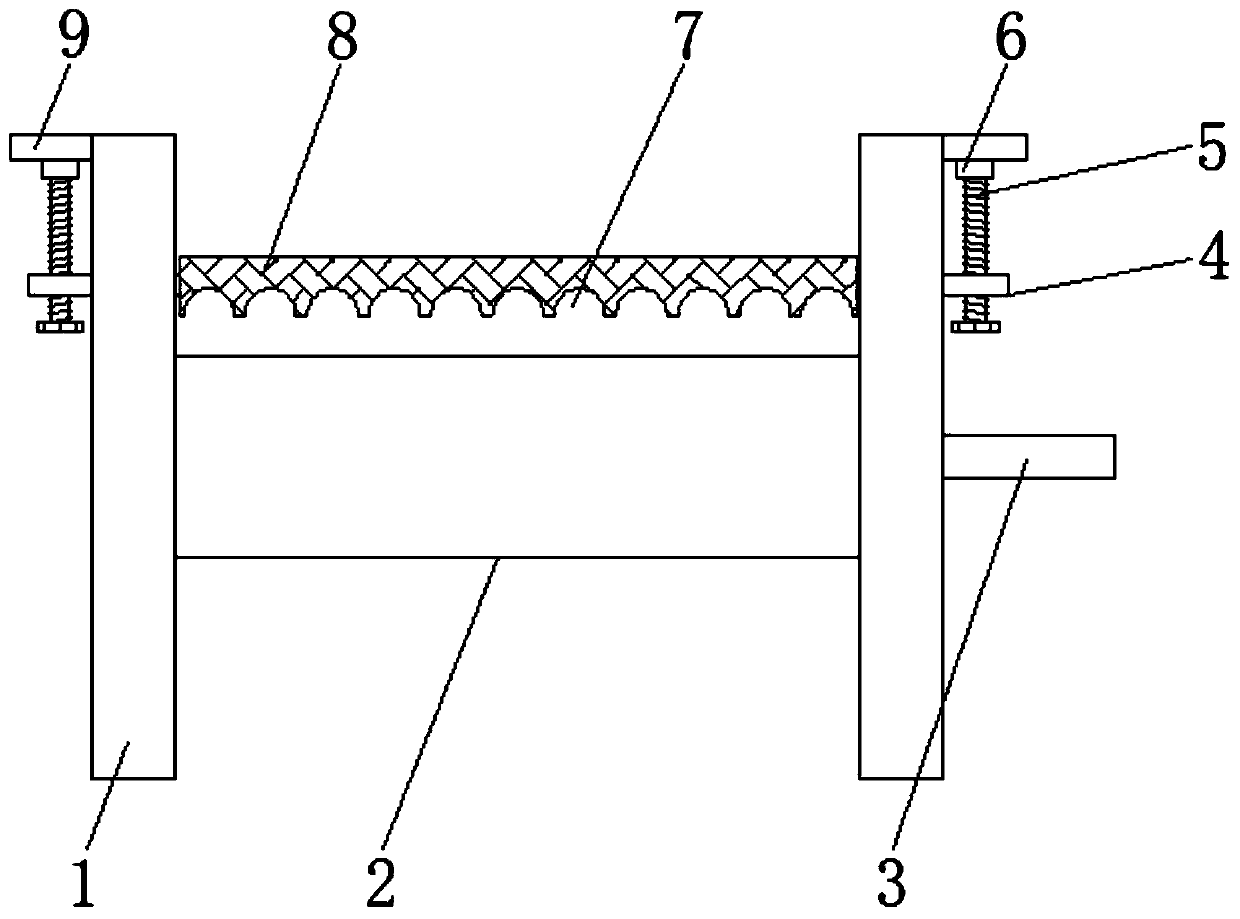
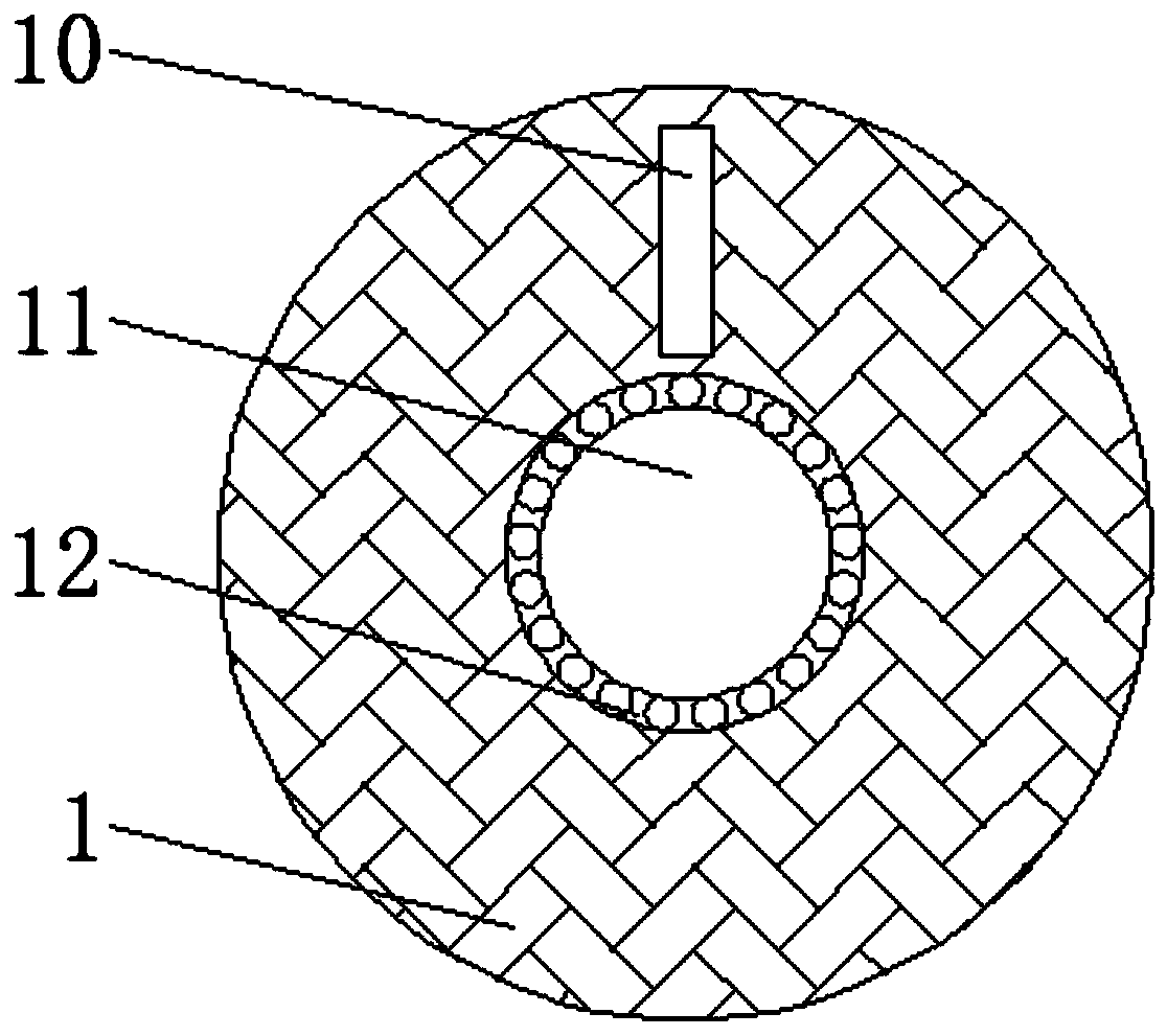
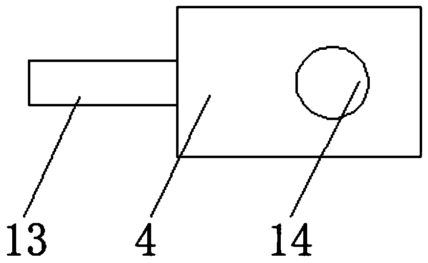
[0020] see Figure 1-5 , a winding device for optical fibers, including a positioning ring plate 1, the number of positioning ring plates 1 is two, and a winding cylinder 2 is arranged laterally at the center of the corresponding side of the two positioning ring plates 1, and is positioned on the right side The center of the right side surface of the ring plate 1 is provided with a rotating rod 3, the top of the center of the outer surface of the positioning r...


PUM


Abstract

The invention discloses winding equipment for optical fibers. The winding equipment comprises positioning ring plates; two positioning ring plates are provided; winding cylinders are transversely arranged in the centers of the corresponding sides of the two positioning ring plates; a rotating rod is arranged in the center of the right side surface of the positioning ring plate on the right side; connecting plates are fixedly connected to the tops of the centers of the outer side surfaces of the positioning ring plates; and fixed sleeves are fixedly connected to the centers of the bottom surfaces of the connecting plates. Through cooperative use of lifting plates, rotating screw rods, the fixed sleeves, arc pressing grooves, pressing plates, the connecting plates, chutes and slide plates, wound optical fibers can be limited, so that the scattering of optical fiber discs is effectively prevented, the problem of weaker optical fiber winding effect by the winding equipment caused by easy scattering of the optical fiber discs due to incapability of limiting the optical fibers after winding by the winding equipment is solved, and the practicability of the winding equipment is greatly improved.

Description

technical field [0001] The invention relates to the technical field of communication, in particular to a winding device for optical fibers. Background technique [0002] With the development of the communication industry in modern society, optical fibers have been widely used. During the use of existing optical fibers, winding equipment is required. When winding optical fibers, existing winding equipment cannot limit the position of the optical fibers after winding. In this way, the optical fiber reel is likely to be loose on the winding device, which leads to the problem that the winding device has a poor winding effect on the optical fiber, and greatly reduces the practicability of the winding device. Contents of the invention [0003] The object of the present invention is to provide a winding device for optical fiber, which has the advantage of limiting the position of the wound optical fiber, and solves the problem of poor winding effect of the winding device. [000...

Claims


Application Information

Patent Timeline
Patent Type & Authority Applications(China)
IPC IPC(8): B65H54/54B65H54/70
CPCB65H54/54B65H54/70B65H2701/32
Inventor 张明进
Owner 南通光烁通信设备有限公司
Why Eureka
Try Eureka