Electric fan

An electric fan and fan technology, applied in the field of electric fans, can solve the problem of difficult control of the locking torque of the bracket for installing the motor casing and fan blades, and achieve the effects of stable size, stable installation, and simple and convenient installation

Pending Publication Date: 2020-01-14
GREE ELECTRIC APPLIANCES INC OF ZHUHAI
View PDF0 Cites 0 Cited by
  • Summary
  • Abstract
  • Description
  • Claims
  • Application Information

AI Technical Summary

Problems solved by technology

[0003] Therefore, the technical problem to be solved by the present invention is to overcome the defect in the prior art that it is difficult to control the torque fo

Method used


Image

  • Electric fan
  • Electric fan
  • Electric fan

Examples


Example Embodiment

[0053] Example 1

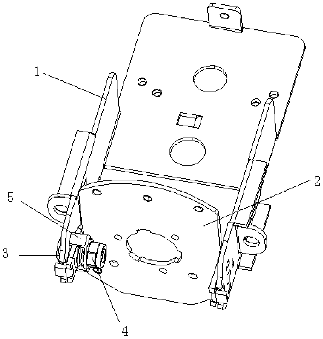
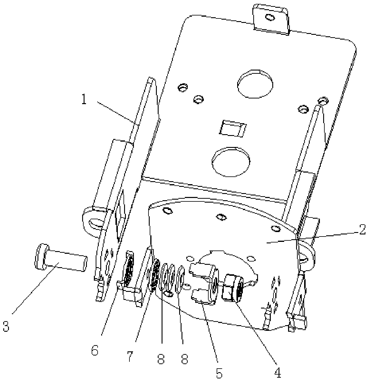
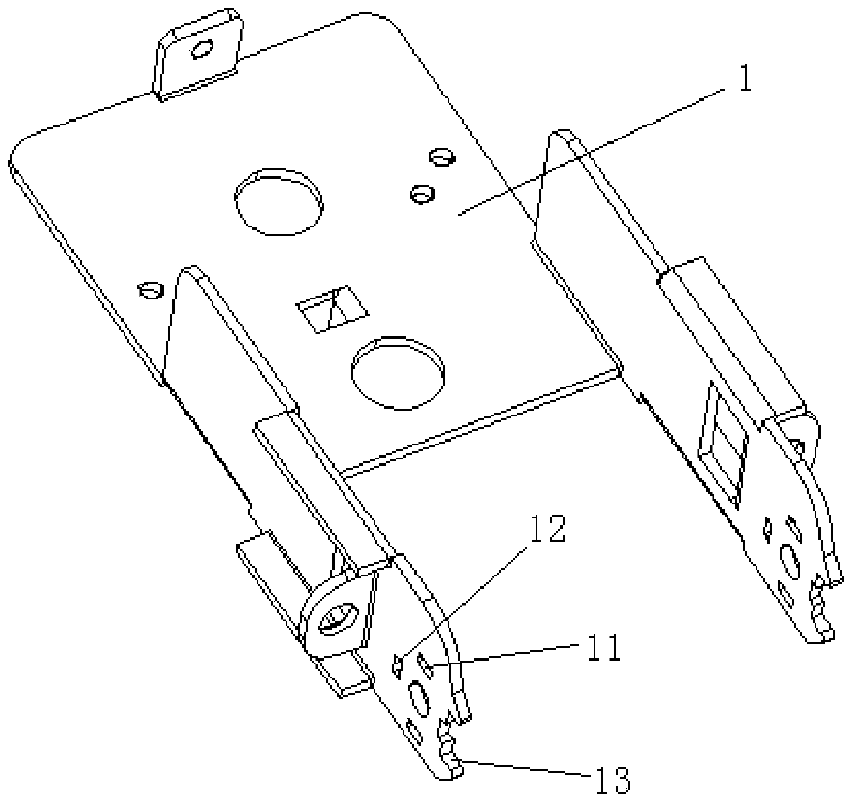
[0054] This embodiment provides a specific implementation of an electric fan, such as Figure 1 to Figure 7 As shown, it includes a first bracket 1 , a second bracket 2 , a fastener 4 , and a stopper 5 .

[0055] Wherein the first bracket 1 is suitable for being fixedly connected with the fuselage, and during the working process, the first bracket 1 is fixed; Rotationally connected to the first bracket 1, the fan head includes a motor that drives the fan blades to rotate, and the fan blades, the rotation of the second bracket 2 specifically refers to the rotation within a certain angle range in the vertical plane; the fastener 4 It is used to fix the second bracket 2 on the hinge shaft 3; the stopper 5 is connected to the first bracket 1, and is located between the first bracket 1 and the fastener 4, with To limit the distance between the fastener 4 and the first bracket 1 , the second bracket 2 is limited between the first bracket 1 and the limiting membe...


PUM


Abstract

The invention relates to an electric fan. The electric fan comprises a first bracket, a second bracket, a fastener and a limiting member, wherein the first bracket is fixedly connected to a body; thesecond bracket is fixedly connected to a fan head, and is rotatably connected to the first bracket through a hinge shaft; the fastener is used for fixing the second bracket on the hinge shaft; the limiting member is connected to the first bracket and located between the first bracket and the fastener, and is used for limiting the distance between the fastener and the first bracket; the second bracket is limited between the first bracket and the limiting member to be connected with the limiting member on the first bracket; and the first limiting member is located between the first bracket and the fastener, and limits the distance between the fastener and the first bracket, so that the fastener fixes the position of the second bracket. Therefore, the torque for locking the second bracket isensured, and for the electric fans of the same model, the torque for locking the second bracket is stable.

Description

technical field [0001] The invention relates to the technical field of electric fans, in particular to an electric fan. Background technique [0002] At present, the electric fan mainly consists of three parts: the head assembly, the fuselage and the support assembly. The body is mainly composed of marbles, torsion springs and springs. The torsion springs and springs are prone to mechanical fatigue during use, which will cause the positioning of the pitch mechanism to fail or be damaged, and the assembly process is also relatively complicated. In the prior art, gaskets + rotating shafts + bolts are used to lock the brackets for installing the motor casing and fan blade after adjusting the pitch angle. When the bolts are manually locked, the torque is difficult to control, and sometimes the torque is too large , Sometimes the torque is too small. When the torque is too large, the contact between the bracket and the fuselage is too tight, and it is difficult to adjust the pit...

Claims


Application Information

Patent Timeline
IPC IPC(8): F04D29/64F04D29/00F04D25/10
CPCF04D25/105F04D29/002F04D29/646
Inventor 王勇黄少杰冯爽杨光霁韦成
Owner GREE ELECTRIC APPLIANCES INC OF ZHUHAI
Why Eureka
Try Eureka