Locking device for guide rail

A technology of locking device and guide rail, applied in the field of locking device of guide rail, can solve the problem of no locking device, etc., and achieve the effect of a safe and reliable locking structure

Inactive Publication Date: 2020-01-14
天津强森机械零部件有限公司
View PDF0 Cites 0 Cited by
  • Summary
  • Abstract
  • Description
  • Claims
  • Application Information

AI Technical Summary

Problems solved by technology

[0010] The guide rail slider is a flat low pair structure commonly used in production, but there is no convenient and reliable locking device in the guide rail slider pair at present

Method used


Image

  • Locking device for guide rail
  • Locking device for guide rail
  • Locking device for guide rail

Examples


Embodiment Construction

[0035] Below, the present invention is described in detail with reference to accompanying drawing and embodiment:

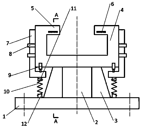
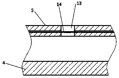
[0036] Such as Figure 1~3 As shown, a locking device for a guide rail includes a bottom plate 1, a guide groove 4 is arranged on the bottom plate 1, a groove body for accommodating a sliding slider is formed in the guide groove 4, and the upper end of the groove body is provided with a The limit plate 5 from which the slider is disengaged, the spring plate installation groove 6 is arranged in the limit plate 5 along the moving direction of the slide block, the driving groove 13 is formed in the limit plate 5 along the direction vertical to the slide block, and the spring plate The friction shrapnel 14 of the deceleration lock sliding slider is installed in the installation groove 6 , and the driving assembly for driving the friction shrapnel 14 is arranged in the shrapnel installation groove 6 .

[0037] A support block 2 is provided on the bottom plate 1 , and...


PUM


Abstract

The invention discloses a locking device for a guide rail. The locking device includes a bottom plate. The bottom plate is provided with a guide groove. A groove body for accommodating a slide slideris formed in the guide groove, the upper end of the groove body is provided with a limiting plate for preventing the slide slider from detaching, an elastic sheet mounting groove is formed in the limiting plate in the moving direction of the slide slider, a driving groove is formed in the limiting plate in the direction vertical to the slide slider, a friction elastic sheet for decelerating and locking the slide slider is installed in the elastic sheet mounting groove, and the elastic sheet mounting groove is provided with a driving component for driving the friction elastic sheet. By means ofthe locking device, a driving rod moves downwards to drive a driving boss to move along a driving groove, the friction elastic sheet is extruded, and therefore the volume of the groove body in the guide groove is reduced, the slide slider and the friction elastic sheet are in friction, and the aim of deceleration or locking is achieved; and lifting guiding of the driving rod is achieved through alimit buckle, driving of the driving rod is realized through a driving cylinder, and resetting of the driving rod is realized through a return spring.

Description

technical field [0001] The invention belongs to a component of a sliding structure, in particular to a locking device of a guide rail. Background technique [0002] A kinematic pair is an active connection in which two components are in direct contact and can produce relative motion. [0003] Elements such as points, lines, and surfaces in which two or more components participate in contact to form a kinematic pair are called kinematic pair elements. [0004] There are several ways to classify sports activities: [0005] Classification according to the contact form of the kinematic pair: the kinematic pair in surface-to-surface contact has a lower pressure in the contact part, which is called a low pair, while the kinematic pair in point or line contact is called a high pair, and the high pair is easier to wear than the low pair. [0006] The low pair generally has a rotating pair, a moving pair, and a screw pair, and the high pair includes wheels and rails, cams and follo...

Claims


Application Information

Patent Timeline
Patent Type & Authority Applications(China)
IPC IPC(8): F16C29/10F16C29/02F16D63/00
CPCF16C29/02F16C29/10F16D63/008
Inventor 韩树森
Owner 天津强森机械零部件有限公司
Why Eureka
Try Eureka