Lamination type fire hole assembly

A lamination type, fire hole technology, applied in the direction of gas fuel burner, combustion method, combustion type, etc., can solve the problems of poor combustion and large fire hole, etc., to improve the deterioration of exhaust emissions, the stability of combustion flame, and the stability of expansion. The effect of the burn zone

Pending Publication Date: 2020-01-14
VATTI CORP LTD
View PDF0 Cites 2 Cited by
  • Summary
  • Abstract
  • Description
  • Claims
  • Application Information

AI Technical Summary

Problems solved by technology

[0003] In view of this, the main purpose of the present invention is to provide a laminated fire hole assembly, which solves the fire hole structure, the physical phenomenon of sublimation after long-term combustion, resulting in larger and larger fire holes and poor combustion.

Method used


Image

  • Lamination type fire hole assembly
  • Lamination type fire hole assembly
  • Lamination type fire hole assembly

Examples


Embodiment 1

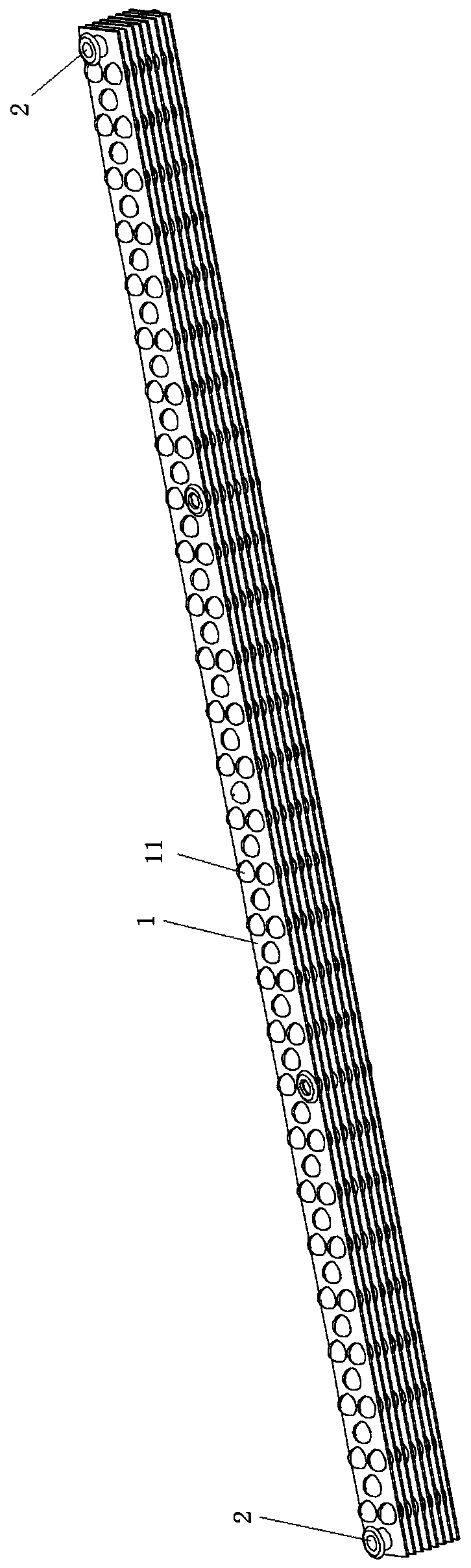
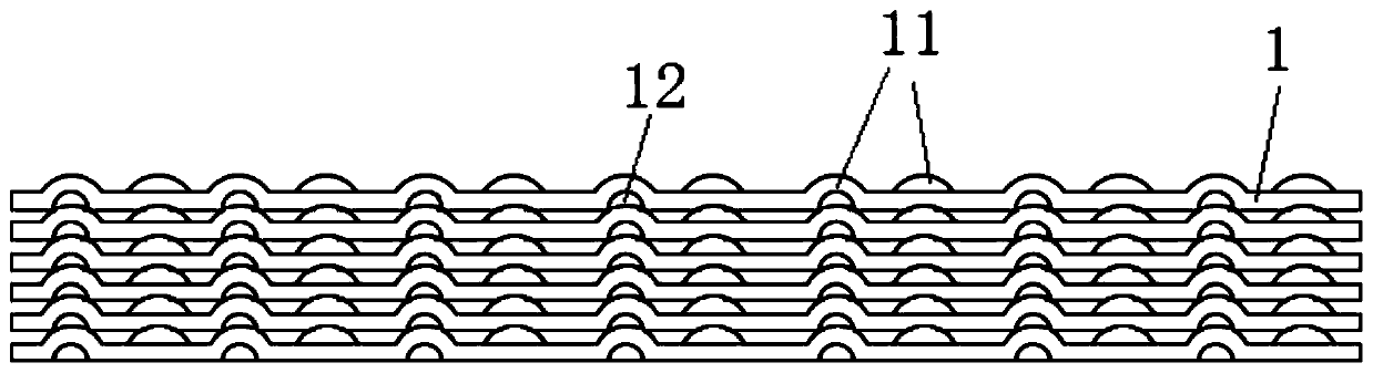
[0030] Embodiment 1 of the present invention provides a laminated fire hole assembly, such as figure 1 , figure 2 , image 3 , Figure 4 , Figure 5 As shown, for a burner, the fire hole assembly includes several laminations 1 stacked on top of each other, and the front of each lamination 1 is provided with several convex parts 11 facing in the same direction, each of the laminations 1 Recesses 12 are provided at positions corresponding to the protrusions 11 on the back of the sheet 1 , and the protrusions 11 and the inner recesses 12 disposed on adjacent laminations 1 correspond to each other.

[0031] By adopting the above-mentioned fire hole assembly, its depth is longer, and the loss of long-term combustion sublimation will not affect the size change of the fire hole, and the thin plate at the non-fire hole position plays a role of stabilizing the flame, making the combustion flame more stable; In addition, through The fire hole assembly with the structure of the pres...

Embodiment 2

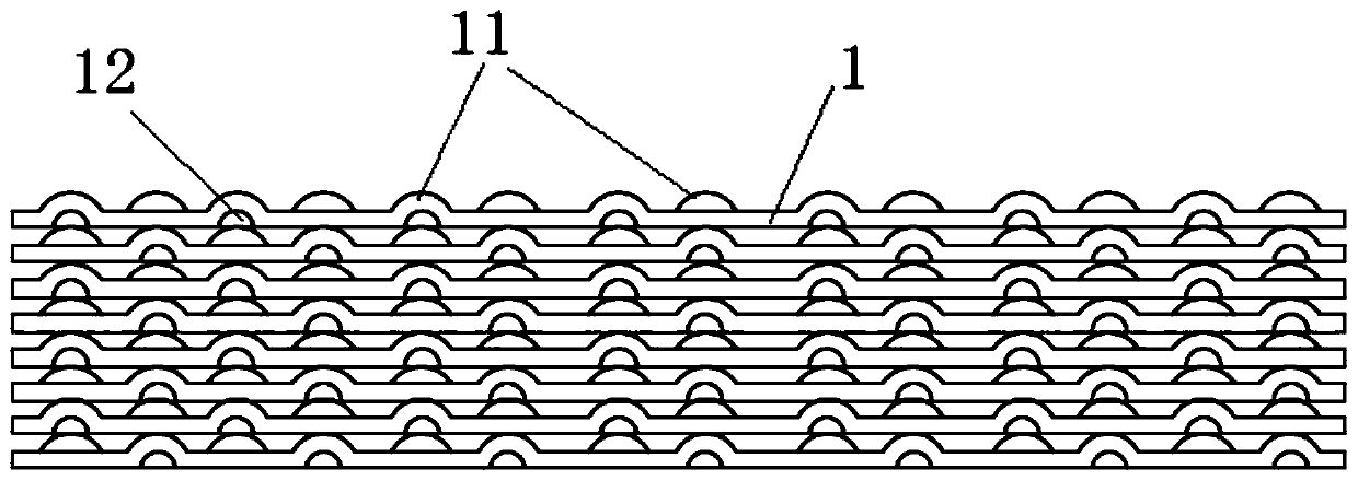
[0041] Embodiment 2 of the present invention provides a laminated fire hole assembly for burners. The fire hole assembly includes several laminates 1 stacked on top of each other. The front of each of the laminates 1 is provided with a There are several convex parts 11 on the back side of each lamination 1 corresponding to the position of the convex part 11, and an inner concave part 12 is provided at the position corresponding to the protruding part 11, and the convex part provided on the adjacent lamination 1 The raised portion 11 corresponds to the inner concave portion 12 .

[0042] By adopting the above-mentioned fire hole assembly, its depth is longer, and the loss of long-term combustion sublimation will not affect the size change of the fire hole, and the thin plate at the non-fire hole position plays a role of stabilizing the flame, making the combustion flame more stable; In addition, through The fire hole assembly with the structure of the present invention also imp...


PUM


Abstract

The invention discloses a lamination type fire hole assembly. The fire hole assembly comprises multiple lamination pieces laminated and stacked, the front face of each lamination piece is provided with multiple protrusion parts with consistent orientations, the positions, corresponding to the protrusion parts, of the back face of each lamination piece are provided with inward concave parts, and the protrusion parts and the inwards concave parts on the adjacent lamination pieces correspond to one another. Through the fire hole assembly of the structure, the longitudinal depth is large, losses caused by long-term combustion sublimation cannot affect the size change of a fire hole, a sheet on the non fire hole position achieves the flame stabilizing effect, and the combustion flames are morestable; in addition, through the fire hole assembly of the structure, the service life of a gas combustor is prolonged, the problem of deterioration of waste gas emissions after long-term combustion can be solved, meanwhile, the stable combustion section of the gas combustor can be expanded, tempering of the gas combustor and the floating-flame probability can be reduced, and a gas stove product of the gas combustor with the fire hole assembly is more environment-friendly.

Description

technical field [0001] The invention belongs to the technical field of gas burners, and in particular relates to a laminated fire hole assembly. Background technique [0002] Existing gas burners generally use sheet metal (thin plate) punched combustion fire hole structure, this kind of fire hole structure is easy to mass-produce, and the cost is low, but there is a common problem that the fire hole becomes larger and the combustion becomes worse after long-term use , the fundamental problem is that the existing sheet metal has a physical phenomenon of sublimation after long-term combustion, which leads to larger and larger fire holes, worse combustion, and increased waste emissions. If the thickness of the sheet metal is increased, the processing difficulty and manufacturing will be significantly increased. Therefore, the existing ideas are basically unable to solve the problems faced by the existing gas burners; moreover, the thin plate structure of the existing gas burner...

Claims


Application Information

Patent Timeline
Patent Type & Authority Applications(China)
IPC IPC(8): F23D14/02F23D14/46
CPCF23D14/02F23D14/46
Inventor 陈耀华潘叶江
Owner VATTI CORP LTD
Why Eureka
Try Eureka