
Portable plane elastic array scroll heat exchange device

A heat exchange device, portable technology, applied in the direction of heat exchanger types, indirect heat exchangers, fixed tubular conduit components, etc., can solve the problem of low flexibility of multiple heat exchange devices, ineffective heat transfer enhancement, and high efficiency. , flexibility and other issues, to achieve the effect of uniform vibration, not easy to fatigue damage, flexible assembly and disassembly

Pending Publication Date: 2020-01-14
ANHUI UNIV OF SCI & TECH
View PDF0 Cites 2 Cited by
  • Summary
  • Abstract
  • Description
  • Claims
  • Application Information

AI Technical Summary

Problems solved by technology

However, due to the limitations of the internal tube bundle arrangement and the overall size of this elastic tube bundle heat exchange device, the enhanced heat transfer effect is not obvious, and the flexibility of combining multiple heat exchange devices is low.
Based on the problems existing in the above-mentioned heat exchange device, it cannot meet the needs of high efficiency and flexibility

Method used


Image

  • Portable plane elastic array scroll heat exchange device
  • Portable plane elastic array scroll heat exchange device
  • Portable plane elastic array scroll heat exchange device

Examples


Embodiment Construction

[0016] In order to make the object, technical solution and advantages of the present invention clearer, the present invention will be further described in detail below in conjunction with the accompanying drawings and embodiments. It should be understood that the specific embodiments described here are only used to explain the present invention, not to limit the present invention.

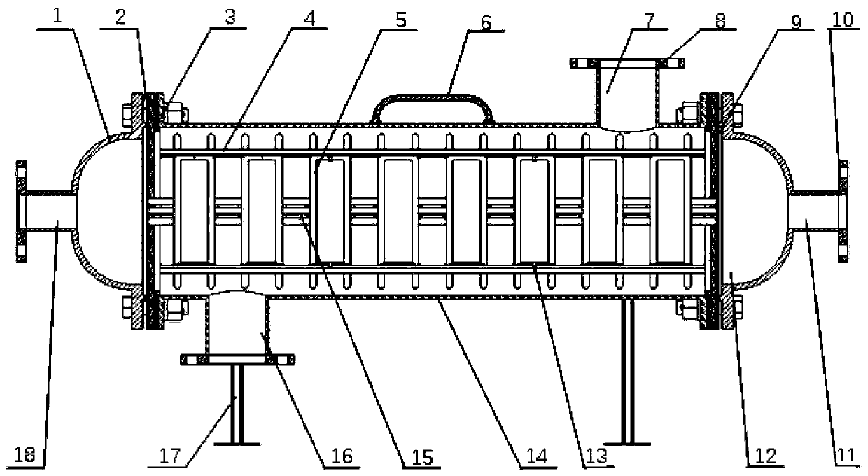
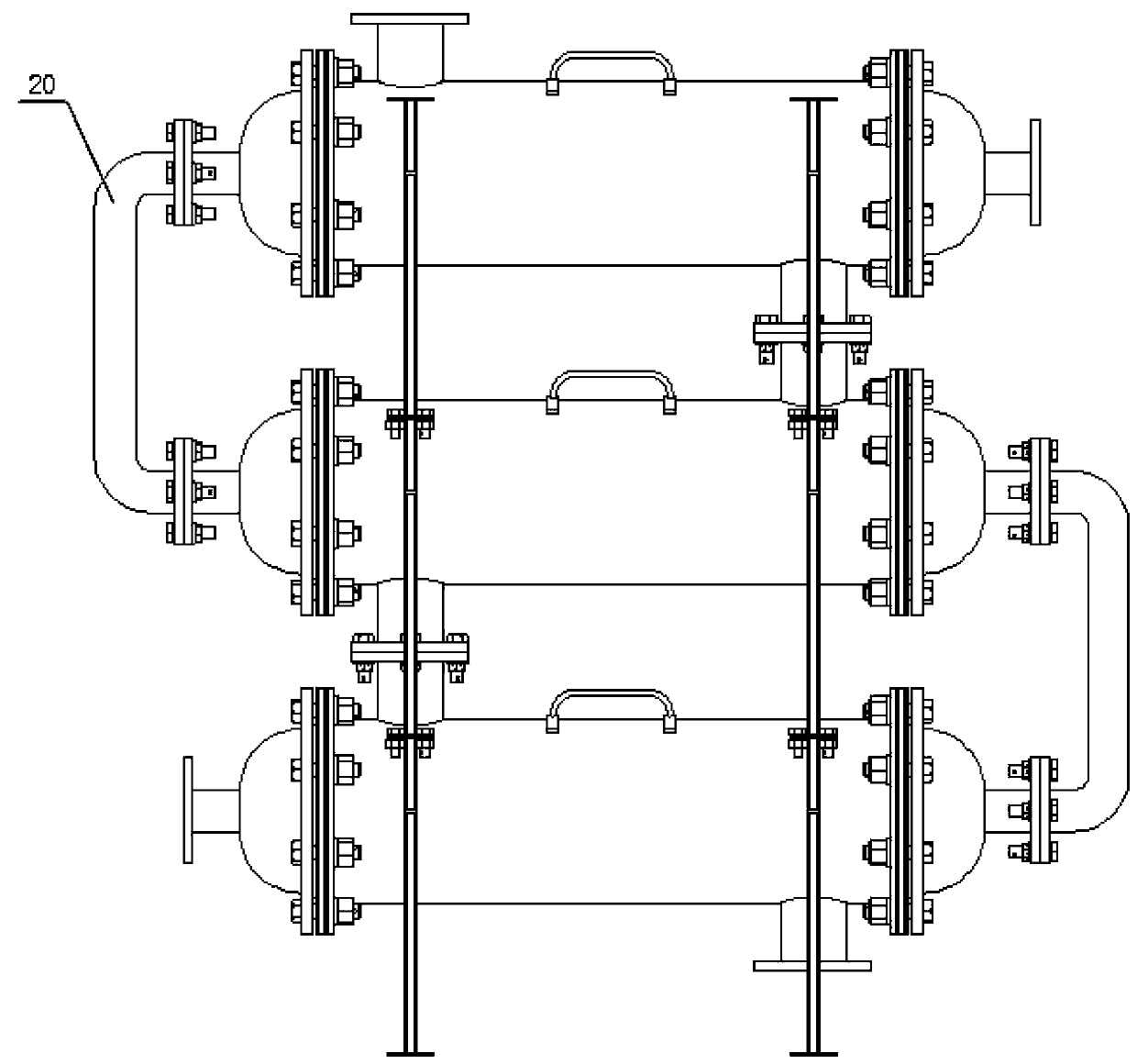
[0017] see figure 1 , figure 2 with image 3 , figure 1 It is a structural schematic diagram of the present invention, figure 2 It is the internal structure diagram of the present invention, image 3 It is a schematic diagram of multiple combined installation structures of the present invention.

[0018] The portable planar elastic array scroll tube heat exchange device includes a left head 1, a gasket 2, a tube plate left end cover 3, a tube plate fixing frame 4, an elastic scroll tube bundle 5, a handle 6, and a shell side outlet pipe 7 , flange 8, tube plate right end cover 9, flange 10,...


PUM


Abstract

The invention relates to a portable plane elastic array scroll heat exchange device. The device comprises a left seal, a right seal, a pipe pass outlet pipe, plane elastic scrolls, a pipe pass inlet pipe, mass blocks, a cylinder, flanges, gaskets, a pipe plate fixed frame, pipe plate end covers, a pipe plate fixed lantern ring, a shell pass outlet pipe, a shell pass inlet pipe, a bracket and a handle. The plane elastic scrolls consist of red copper plane scrolls and the mass blocks; the plane elastic scrolls are arranged to form pipe bundles at equal intervals, and are connected to the pipe plate fixed frame through fixed lantern rings; the mass blocks are connected between the plane elastic scrolls; the cylinder is fixedly connected out of a pipe plate; the gaskets are arranged between the left and right pipe plate end covers and between the end covers and the cylinder for sealing; the left and right seals are fixedly connected with the other ends of the left and right pipe plate endcovers; and the gaskets are arranged between the left and right pipe plate end covers and the seals for sealing. The heat exchange device uses vibration for realizing enhanced heat transfer; the planescrolls adopt red copper, so that copper pipes are not easy to break, the service life is prolonged, the noise harm is reduced, and the effect of automatically removing incrustations can be achieved;through the effect of the mass blocks, the inherent characteristics of the pipe bundles are changed, the vibration characteristics under fluid induction are adjusted, and the effect of strengtheningthe heat transfer through vibration is further achieved; and through arrangement of the flanges and connecting pipes in each inlet and outlet, the single-line / array combined installation of multiple heat exchange devices can be realized, and the flexible assembly and disassembly according to actual condition demands can be achieved.

Description

technical field [0001] The invention relates to the technical field of heat exchange device design, in particular to a portable planar elastic array scroll tube heat exchange device. Background technique [0002] The heat exchange device is an energy-saving device that transfers heat between two or more fluids at different temperatures. It transfers heat from a fluid with a higher temperature to a fluid with a lower temperature, so that the fluid temperature reaches the index specified in the process. , to meet the needs of process conditions, and is also one of the main equipment to improve energy utilization, widely used in petroleum, chemical, electric power, refrigeration and other industrial fields. [0003] The internal heat exchange element of the traditional shell-and-tube heat exchange device adopts multiple stainless steel straight tubes, the overall structure size is large, and the assembly flexibility is low; the internal heat transfer element of the traditional ...

Claims


Application Information

Patent Timeline
IPC IPC(8): F28D7/08F28F13/10F28F21/08
CPCF28D7/08F28F13/10F28F21/085F28D7/04F28F2255/02
Inventor 季家东张经纬高润淼陈卫强
Owner ANHUI UNIV OF SCI & TECH
Learn More