
Constant-temperature and constant-pressure measuring device for flow of component

A measuring device, a technology of constant temperature and constant pressure, applied in the direction of measuring device, measuring flow/mass flow, liquid/fluid solid measurement, etc., can solve the problems of inaccurate measurement results, inability to effectively control flow, pressure, temperature, etc.

Inactive Publication Date: 2020-01-14
CHONGQING KEBEN TECH
View PDF0 Cites 0 Cited by
  • Summary
  • Abstract
  • Description
  • Claims
  • Application Information

AI Technical Summary

Problems solved by technology

[0003] Since there are many factors affecting the change of flow rate, the flow rate, pressure and temperature cannot be effectively controlled, and the change affecting the passing flow rate cannot be completely determined by the parts themselves, resulting in inaccurate measurement results.

Method used


Image

  • Constant-temperature and constant-pressure measuring device for flow of component
  • Constant-temperature and constant-pressure measuring device for flow of component
  • Constant-temperature and constant-pressure measuring device for flow of component

Examples


Embodiment 1

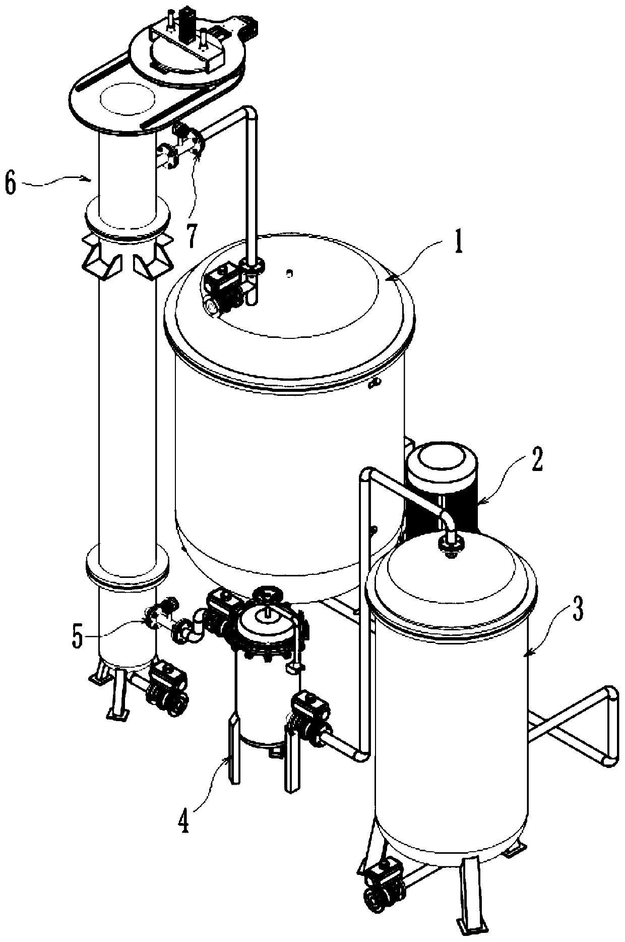
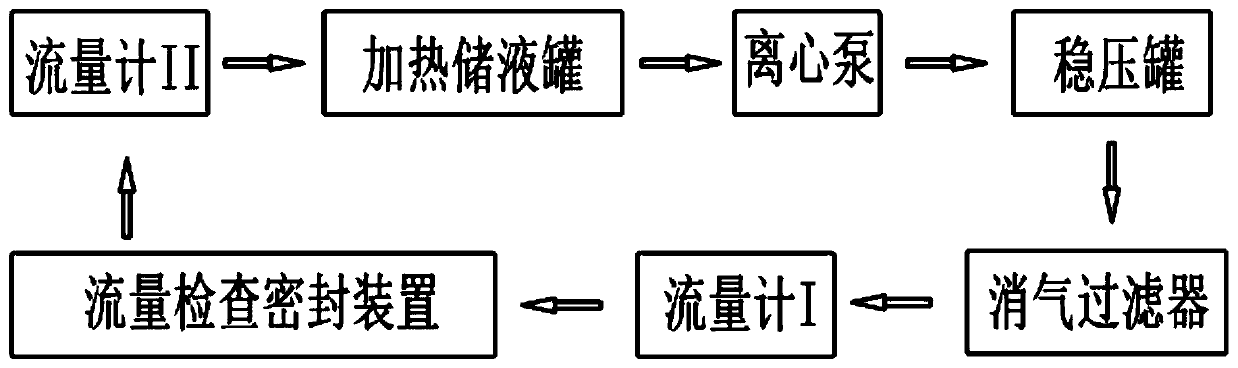
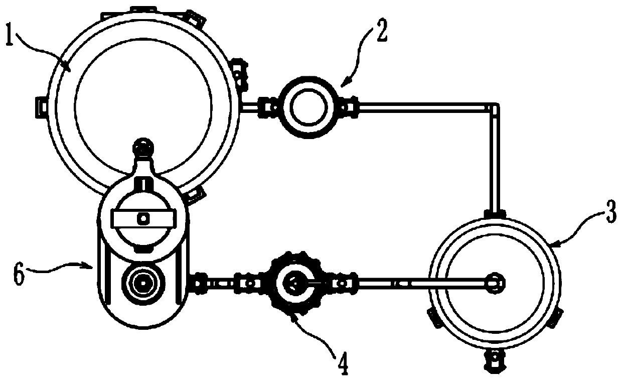
[0019] see Figure 1~3 , in the embodiment of the present invention, a constant temperature and constant pressure measuring device for component flow, including a heating liquid storage tank 1, a centrifugal pump 2, a pressure stabilizing tank 3 and a flow checking sealing device 6 connected in sequence to form a liquid phase cycle, in this implementation In an example, the heating liquid storage tank 1 is used to store the liquid phase and heat it so that the temperature of the liquid phase is constant, and the centrifugal pump 2 is used to pump the liquid phase in the heating liquid storage tank 1 into the surge tank 3 Inside, preferably, the centrifugal pump 2 is a multi-stage centrifugal pump; the surge tank 3, obviously, is used to ensure that the pressure of the liquid phase output to the flow inspection sealing device 6 is stable; the flow inspection sealing device 6 is used for Place the parts to be measured, and connect the inlet and outlet of the parts with the heati...

Embodiment 2

[0022] see Figure 1~3 , in an embodiment of the present invention, a component flow constant temperature and constant pressure measuring device includes a heating liquid storage tank 1, a centrifugal pump 2, a pressure stabilizing tank 3 and a flow inspection sealing device 6 connected in sequence to form a liquid phase cycle. Valves are installed on the pipelines between the liquid storage tank 1, the centrifugal pump 2, the surge tank 3 and the flow inspection sealing device 6. Preferably, the valves are electromagnetic valves, which are convenient for automatic control.

[0023] In order to realize the connection of the pipelines conveniently, the pipelines between the heating liquid storage tank 1, the centrifugal pump 2, the surge tank 3 and the flow inspection sealing device 6 are all equipped with quick joints to realize convenient and fast connection, which is convenient Rapid setup of the entire detection setup.

[0024] Combining Examples 1-2, it is easy to know th...


PUM


Abstract

The invention discloses a constant-temperature and constant-pressure measuring device for the flow of a component, and relates to the technical field of pipeline channel detection of components. The device comprises a heating liquid storage tank, a centrifugal pump, a pressure stabilizing tank and a flow inspection sealing device which are sequentially connected to form liquid phase circulation, wherein the heating liquid storage tank is used for storing a liquid phase and heating the liquid phase to enable the temperature of the liquid phase to be constant, and the centrifugal pump is used for pumping the liquid phase in the heating liquid storage tank into the pressure stabilizing tank; the pressure stabilizing tank is used for ensuring that the pressure of the liquid phase output to theflow checking and sealing device is stable; the flow inspection sealing device is used for placing a component to be measured, enabling the inlet and the outlet of the component to be respectively communicated with the heating liquid storage tank and the pressure stabilizing tank, and the flow inspection sealing device is provided with a flow meter I and a flow meter II at the inlet and the outlet respectively. The circulation loop with a constant-temperature and constant-pressure effect is established, so that the change of the passing flow is completely dependent on the component, and whether an irregular channel in the component meets the design requirements or not is judged.

Description

technical field [0001] The invention relates to the technical field of component pipeline channel detection, in particular to a component flow constant temperature and constant pressure measuring device. Background technique [0002] Flow refers to the amount of fluid flowing through the effective section of a closed pipe or open channel per unit time, also known as instantaneous flow. Nowadays, when it is necessary to measure whether the pipeline channel in the component meets the design requirements, most of them use the liquid flow rate per unit time to detect. Although the method is relatively simple, there are still some problems in practical application: [0003] Since there are many factors affecting the change of the flow rate, the flow rate, pressure and temperature cannot be effectively controlled, and the change affecting the flow rate cannot be completely determined by the components themselves, resulting in inaccurate measurement results. [0004] Based on this...

Claims


Application Information

Patent Timeline
Patent Type & Authority Applications(China)
IPC IPC(8): G01F1/00G05D27/02
CPCG01F1/00G05D27/02
Inventor 朱兴德余虹江徐俊杰肖炎张洋余红
Owner CHONGQING KEBEN TECH
Features
  • Generate Ideas
  • Intellectual Property
  • Life Sciences
  • Materials
  • Tech Scout
  • Unparalleled Data Quality
  • Higher Quality Content
  • 60% Fewer Hallucinations
Learn More