Separator and phase-split conveying method for eliminating plug flow on serious segments by utilizing same

A separator and flow pipe technology, applied in the field of subsea separation and phase-separation transportation, can solve the problems of weakening severe slug flow, intermittent outflow of gas and liquid at the outlet, affecting wellhead pressure, etc., so as to eliminate serious slug flow, liquid level and pressure. Stabilizing and reducing the effect of inlet pressure

Inactive Publication Date: 2005-06-29
XI AN JIAOTONG UNIV
View PDF3 Cites 16 Cited by
  • Summary
  • Abstract
  • Description
  • Claims
  • Application Information

AI Technical Summary

Problems solved by technology

This flow pattern will produce a liquid plug several times the height of the riser, which will cause periodic changes in the pressure in the gathering pipeline, thereby affecting the wellhead pressure, and will also cause the gas and liquid to flow out intermittently at the outlet of the riser, causing the gas to spray at a high speed in a short period of time. out, causing the outlet liquid plug to enter the separator at high speed, and the severe slug flow phenomenon brings many problems to the design and production
As production facilities had to be scaled up, some separators were rated far greater than the actual liquid handling capacity, resulting in waste, and severe flow fluctuations also made it difficult to control separators and downstream processing facilities, sometimes even causing production interruptions
[0003] Chinese patent CN1387617A "Method and system for suppressing and controlling slug flow in multiphase fluid flow" (publication date: December 25, 2002) and US patent US6390114B1 "Method and apparatus for suppressing and controlling slug flow in a multi- phase fluid stream" (publication date: May 21, 2002) announced a severe slug flow suppression method, which uses easy-to-implement gas-liquid single-phase flow measurement combined with multiple control variables such as liquid level and pressure to control Realize the control of severe slug flow; British patent GB2374161A "Gas injection controlling liquid slugs inpipeline riser" (publication date: October 9, 2002) announced a serious slug flow control method of gas injection at the bottom of the riser, However, experiments have shown that this method requires a large amount of gas injection to completely eliminate severe slug flow, and can only weaken severe slug flow when the gas injection amount is small
The above methods only achieve the effect of weakening severe slug flow, but they have not fundamentally eliminated the conditions for severe slug flow

Method used


Image

  • Separator and phase-split conveying method for eliminating plug flow on serious segments by utilizing same
  • Separator and phase-split conveying method for eliminating plug flow on serious segments by utilizing same
  • Separator and phase-split conveying method for eliminating plug flow on serious segments by utilizing same

Examples


Embodiment Construction

[0014] The present invention will be described in further detail below in conjunction with the accompanying drawings.

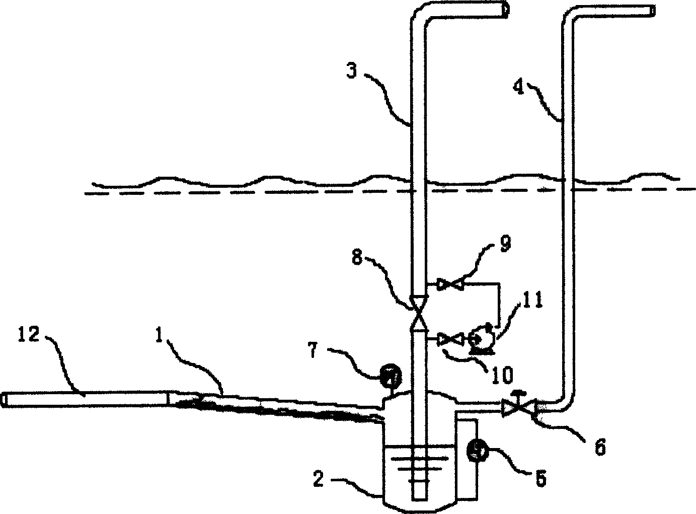
[0015] see figure 1 , the separator includes a shell 2, the shell 2 is connected with the flow pipe 1 and the gas riser 4, the liquid level sensor 5 and the pressure sensor 7 are arranged on the shell 2, the riser 3 is inserted into the shell 2 and extends to the shell At the bottom of the body 2, a valve 8 is installed on the part where the rising pipe 3 protrudes from the shell 2. The valve 8 forms a bypass with the liquid phase pump 11 through the valve 9 and the valve 10 at both ends of the rising pipe 3, and the gas rising pipe 4 is close to the shell. A control valve 6 is provided at the outlet of the body 2 .

[0016] The phase-separated conveying method to eliminate severe slug flow is to install a separator at the junction of the mixed transportation pipeline 12 and the rising pipe 3. The separator adopts tangential centrifugal separation, and its v...


PUM


Abstract

A separator and a phase-splitting conveying method for eliminating severe slug flow by using the separator. The separator includes a shell, which is connected with an incoming flow pipe and a gas riser pipe, and is provided with a liquid level sensor and a pressure sensor on the shell. A riser pipe is inserted and extended to the bottom of the shell, the part of the riser pipe protruding from the shell is provided with a liquid phase pump connected to the riser pipe through a valve, and a control valve is set on the gas riser pipe close to the outlet of the shell. The separator of the present invention is installed at the junction of the mixed pipeline and the rising pipe, the gas-liquid fluid in the mixed pipeline enters the shell of the separator through the incoming flow pipe, and the liquid level signal and pressure signal are used to adjust the control valve. The opening makes the liquid level and pressure stable. After the gas and liquid are separated in the separator, the liquid enters the riser and is pressurized by the liquid phase pump to be transported to the onshore platform device. The gas enters the onshore platform device through the gas riser through the control valve. The invention has a simple structure, can conveniently and accurately control the flow of gas and liquid, and achieves the purpose of eliminating severe slug flow.

Description

technical field [0001] The invention relates to a separator and a method for eliminating severe slug flow by using the separator, in particular to a separator for mixed transportation of oil and gas and a seabed separation and phase-separation transportation method for eliminating severe slug flow by using the same. Background technique [0002] In offshore oil exploitation, it is often encountered that gas and liquid are transported at the same time. When the multi-phase gathering and transportation pipeline on the seabed reaches the offshore platform or onshore processing facility, it needs to be connected with the riser. Under certain conditions, the gathering and transportation pipeline and A detrimental flow pattern known as severe slug can occur in systems consisting of risers. This flow pattern will produce a liquid plug several times the height of the riser, which will cause periodic changes in the pressure in the gathering pipeline, thereby affecting the wellhead pr...

Claims


Application Information

Patent Timeline
Patent Type & Authority Applications(China)
IPC IPC(8): B01D19/00E21B43/01E21B43/36F17D3/01
Inventor 郭烈锦张西民王鑫
Owner XI AN JIAOTONG UNIV
Why Eureka
Try Eureka