Fluid leak containment system

a leak containment and flue gas technology, applied in water cleaning, borehole/well accessories, construction, etc., can solve the problems of affecting commercial fisheries and other maritime activities, posing horrific risks to sea life and marine food sources, and oil leakage can be effectively captured, contained and recovered

Inactive Publication Date: 2012-02-02
SHIFFERAW TESSEMA DOSHO
View PDF5 Cites 17 Cited by
  • Summary
  • Abstract
  • Description
  • Claims
  • Application Information

AI Technical Summary

Benefits of technology

[0010]An advantage of this invention is that the fluid leak containment system may be used to effectively capture, contain and recover, oil leaking from an underwater site, such as, but not limited to, a ruptured, underwater extraction site.
[0011]Another advantage of this invention is that the fluid leak containment system may be stored in a manner enabling quick deployment beneath an oil rig or on the deck of vessel.
[0012]Yet another advantage of this invention is that the fluid leak containment system may be deployed one on top of the other in a repetitive arrangement for additional safety.

Problems solved by technology

Underwater oil spills pose horrific risks to sea life and marine food sources for human populations in close proximity to the oil spill.
In addition, underwater oil spills that occur close to the coast impact commercial fisheries and other maritime activities.

Method used


Image

  • Fluid leak containment system
  • Fluid leak containment system
  • Fluid leak containment system

Examples


Embodiment Construction

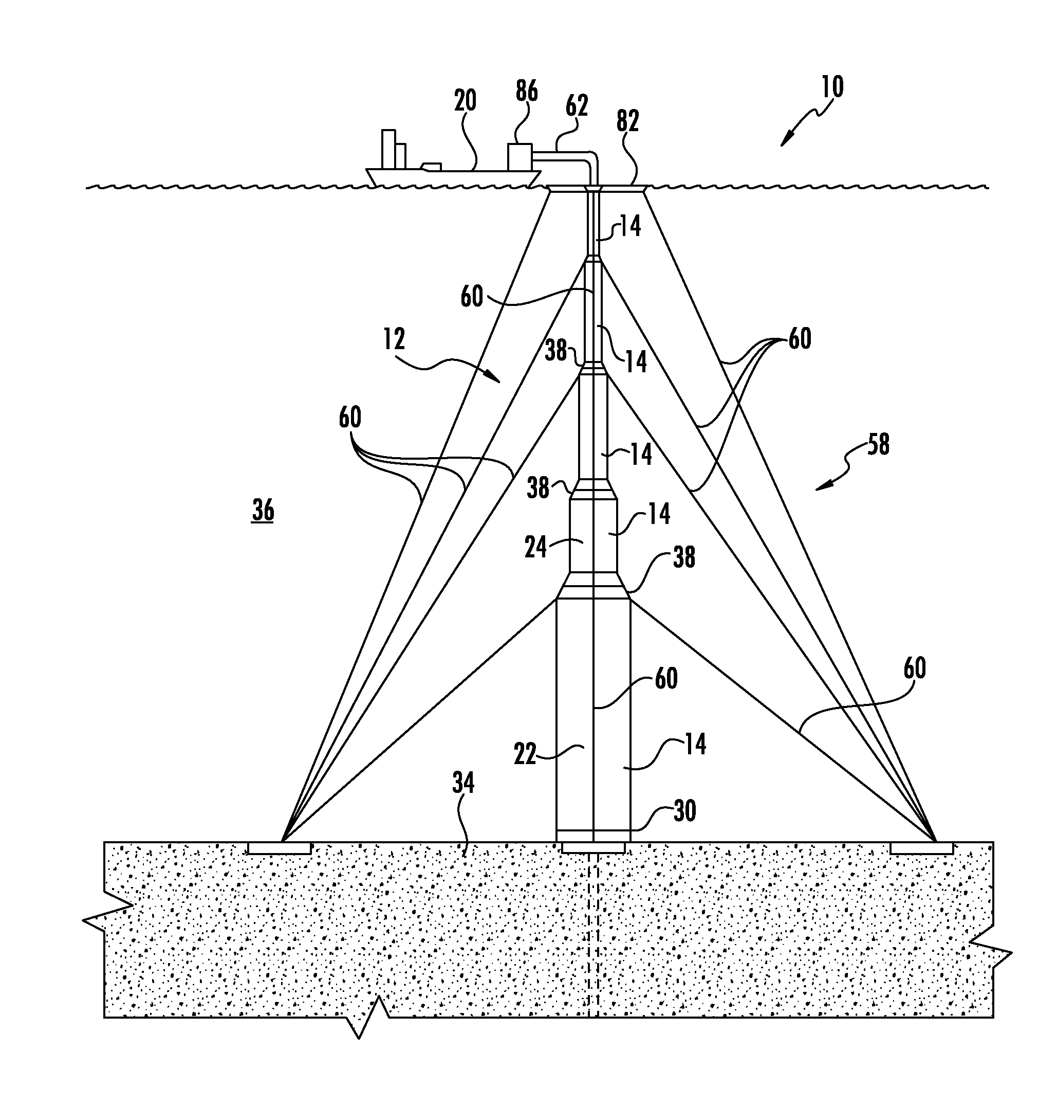
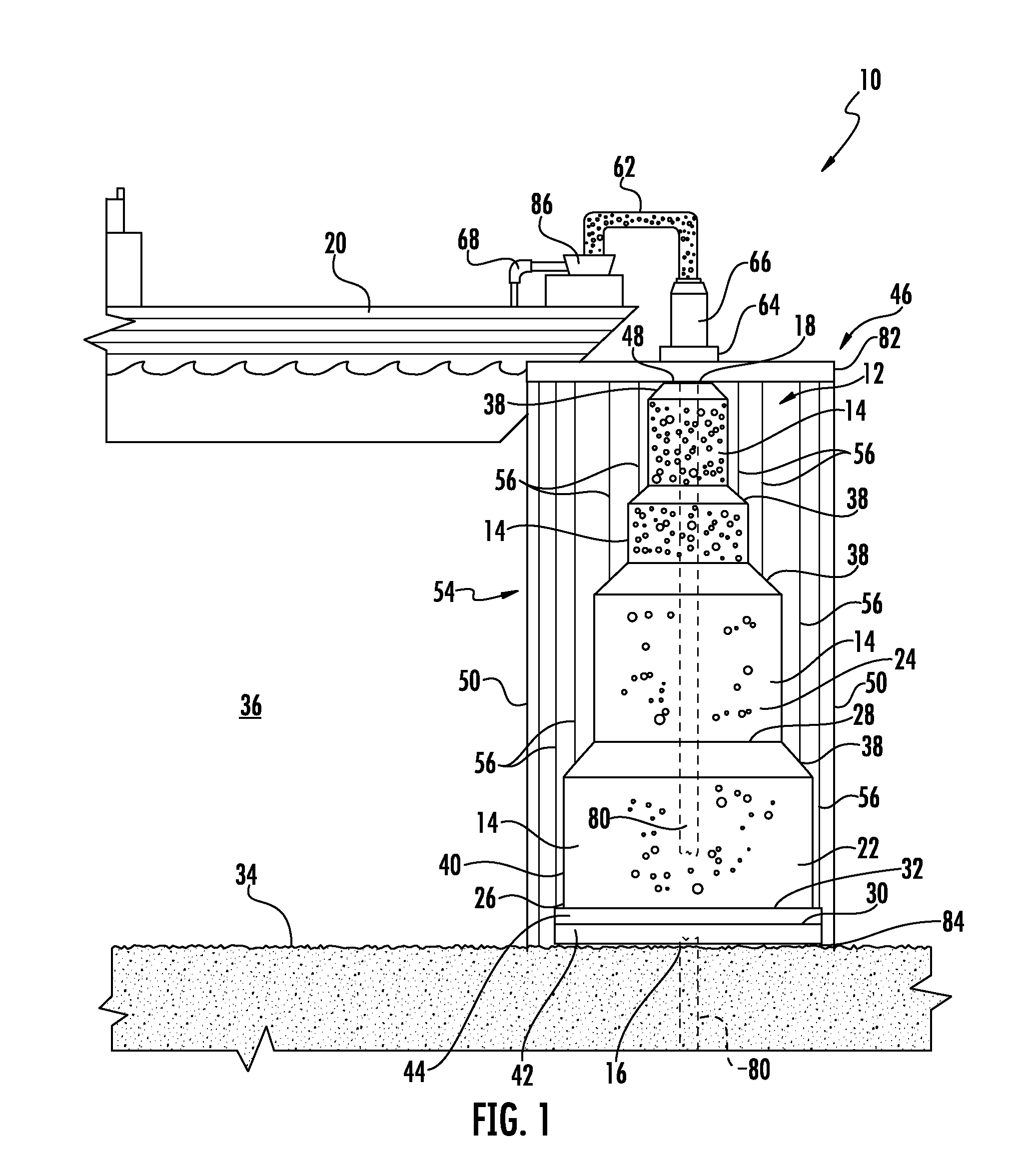
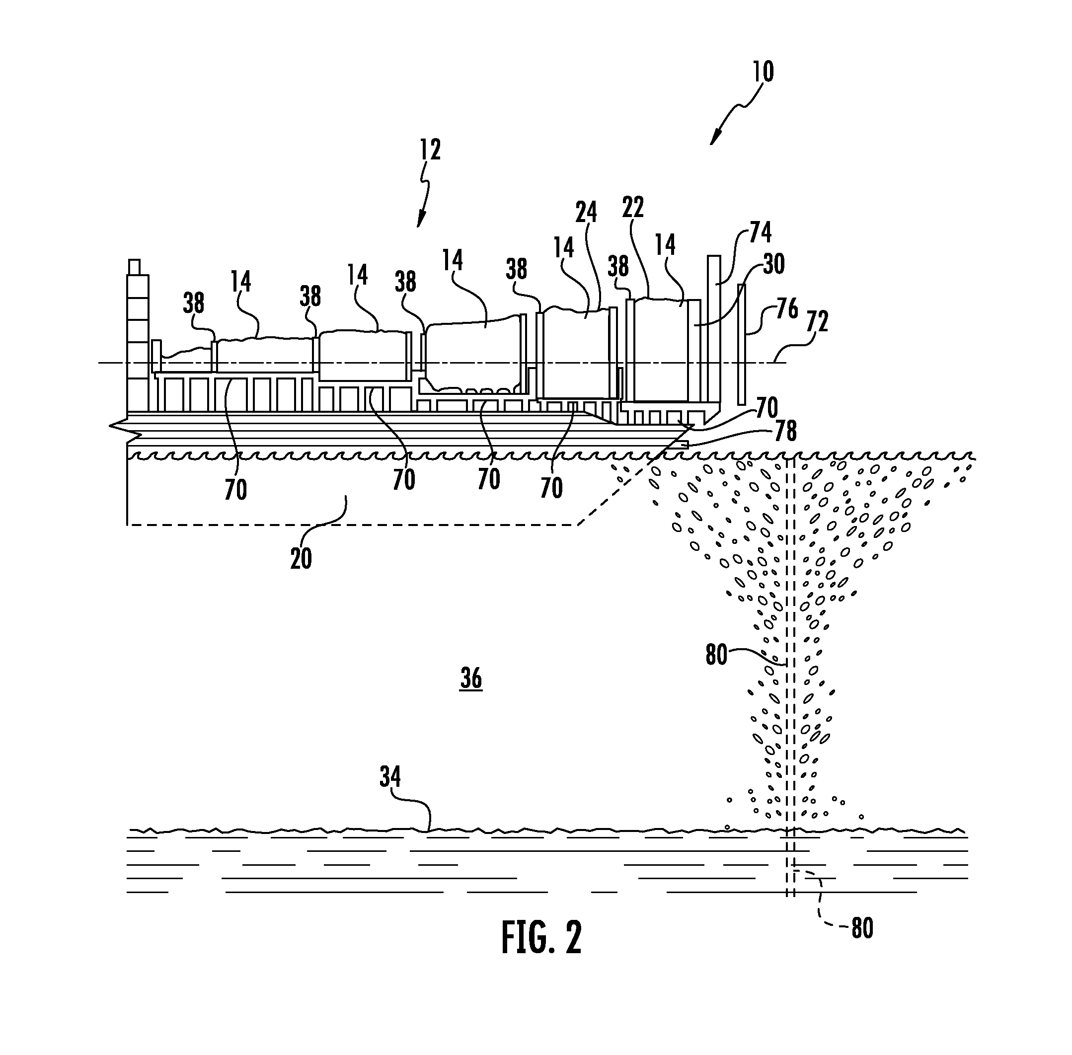
[0026]As shown in FIGS. 1-11, a fluid leak containment system 10 for containing leaks of fluids, such as, but not limited to, fossil fuels, such as oil and natural gas, during an underwater extraction process is disclosed. The fluid leak containment system 10 may contain fluids leaking from a leaking well 80 having a broken casing or pipe extending from a bottom 34 of a water body 36, such as an ocean floor. The fluid leak containment system 10 may be formed from an extendible containment housing 12 formed from a plurality of decreasingly sized housing sections 14 extending from an inlet 16 to an outlet 18 that is smaller than the inlet 16, thereby forming a generally conically shaped containment structure, as shown in FIGS. 1, 7 and 8. The housing sections 14 may be formed from flexible materials that enable easy storage and rapid deployment. The outlet 18 may be configured to exhaust captured fossil fuels into a fluid containment device 20, such as, but not limited to, a vessel. I...


PUM


Abstract

A fluid leak containment system for containing leaks of fluids, such as, but not limited to fossil fuels, during an underwater extraction process is disclosed. The fluid leak containment system may be formed from a generally extendible, conically shaped containment structure including a plurality of decreasingly sized housing sections extending from an inlet to a smaller sized outlet. The housing sections may be formed from flexible materials that enable easy storage and rapid deployment. The outlet directs fossil fuels into a fluid containment device, such as, but not limited to, a vessel. The extendible containment housing may include an anchoring base configured to retain an inlet of the housing section at a bottom of a water body at a leak site such that the inlet envelopes the leak site yet also enables water from outside the first extendible containment housing section to enter the housing, thereby providing for pressure stabilization.

Description

CROSS-REFERENCE TO RELATED APPLICATION[0001]This application claims priority to U.S. Provisional Patent Application No. 61 / 344,477, filed Aug. 2, 2010, the entirety of which is incorporated herein.FIELD OF THE INVENTION[0002]This invention is directed generally to fluid leak containment systems, and more particularly to containment systems for containing fluids leaking underwater during extraction efforts.BACKGROUND[0003]The tragic oil spill in the Gulf of Mexico in 2010 has brought awareness to the lack of adequate systems for containing an underwater oil spill. Underwater oil spills pose horrific risks to sea life and marine food sources for human populations in close proximity to the oil spill. In addition, underwater oil spills that occur close to the coast impact commercial fisheries and other maritime activities. The six months that were needed to seal the oil well rupture that caused the Gulf of Mexico underwater oil spill in 2010 has made the need for a fluid leak containmen...

Claims


Application Information

Patent Timeline
Patent Type & Authority Applications(United States)
IPC IPC(8): E02B15/00
CPCE21B43/0122E02B2015/005
Inventor SHIFFERAW, TESSEMA DOSHO
Owner SHIFFERAW TESSEMA DOSHO
Why Eureka
Try Eureka