
Gas-solid two-phase erosion wear testing device

A wear test, gas-solid technology, applied in the direction of testing wear resistance, etc., can solve the problems of long warm-up and stabilization time, long transmission pipeline of gas-solid two-phase flow of components, complex system and other problems

Inactive Publication Date: 2015-04-29
ZHEJIANG SCI-TECH UNIV
View PDF7 Cites 16 Cited by
  • Summary
  • Abstract
  • Description
  • Claims
  • Application Information

AI Technical Summary

Problems solved by technology

[0004] When simulating the high-temperature and high-speed gas-solid two-phase flow test in the laboratory, due to the complexity of the system, many components and the long transmission pipeline of the gas-solid two-phase flow, it takes a long time for preheating and stabilization, and the test operation cost is high. A high-temperature high-speed gas-solid two-phase erosion wear test device

Method used


Image

  • Gas-solid two-phase erosion wear testing device
  • Gas-solid two-phase erosion wear testing device

Examples


Embodiment Construction

[0015] The present invention will be further described below in conjunction with drawings and embodiments.

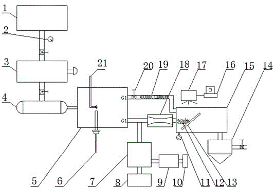
[0016] Such as figure 1 , figure 2 As shown, the structure of the present invention is: the first compressor 1 is connected to the combustion chamber 5 through the surge tank 3 and the drier 4, the outlet of the first compressor 1 is connected to the pressure gauge 2, and the fuel nozzle 21 and the ignition device 6 are installed in the combustion chamber. On the chamber 5, the feeder 9 is connected to the balance 10, and then the second compressor 8 is connected to the particle mixer 7. The high-temperature gas generated in the combustion chamber passes through the needle valve 20 and the auxiliary heating pipe 19, and then connected to the plexiglass for testing. One inlet of section 15, the other way of the high-temperature gas produced by combustion chamber 5 and the outlet of particle mixer 7 particles are connected to another inlet of organic glass test section ...


PUM


Abstract

The invention discloses a gas-solid two-phase erosion wear testing device. A first compressor is connected with a combustion chamber by virtue of a pressure stabilization tank and a dryer; a fuel nozzle and an ignition device are arranged on the combustion chamber; a feeder and a second compressor are connected to a particle mixer; one path of high-temperature gas generated by the combustion chamber passes through a needle valve and an auxiliary heating pipe and then are connected to one inlet of an organic glass test section; another path of the high-temperature gas generated by the combustion chamber and the particle outlet of the particle mixer are connected into the other inlet of the test section by virtue of a two-phase acceleration device; gas-solid two-phase particles in the test section are sprayed to a target material; a thermocouple and a separator are connected with the test section; the separator is communicated with the atmosphere; a CCD camera is aligned with the target material in the test section; and the motion condition of spraying the gas-solid two-phase onto the target material is observed and recorded by using a PIV testing technology and a computer. According to the device disclosed by the invention, the impact rebound rule of spraying the micron-level particles onto the target material and the deformation and corrosion conditions on the target material can be researched.

Description

Technical field [0001] The present invention involves the erosion and wear test device, especially the qi solid two -phase erosion and wear test device. Background technique [0002] There are a large number of gas solid -solid -solid two -phase flow systems in the fields of steel, machinery, and petrochemicals, such as two -phase impeller machinery, power transportation and dust removal devices. Because the fastest speed in the airflow is very high and often deviates from the streamline, it will be right.The wall surface generates erosion wear, which affects normal production and brings hidden dangers of accidents. It is necessary to study the wall wear behavior of the mobility system. [0003] Two methods can be used to reduce the wear of the wall: First, improve the abrasion resistance of the wall surface materials, such as using wear -resistant materials, grinding wear -resistant materials on the wall, or modification of the wall surface.Second, according to the theory of gas...

Claims


Application Information

Patent Timeline
IPC IPC(8): G01N3/56
Inventor 章利特郝李娜王天航施红辉陈婉君
Owner ZHEJIANG SCI-TECH UNIV
Learn More