Engine timing chain tension testing device and method

A test device and engine technology, applied in the direction of engine test, measurement device, mechanical component test, etc., can solve problems such as failure to achieve actual reference value, more simplified models, and reduced accuracy, and achieve a simple and easy-to-understand test method. , The effect of low test cost and convenient construction

Pending Publication Date: 2020-01-14
矩阵汽车有限公司
View PDF0 Cites 1 Cited by
  • Summary
  • Abstract
  • Description
  • Claims
  • Application Information

AI Technical Summary

Problems solved by technology

At present, the evaluation of the force of the engine timing chain mainly relies on the CAE calculation method to evaluate the force of the chain during the actual engine operation. Since the dynamic calculation model of the timing system is relatively complicated, it is directly related to the polygonal benefit of the actual operation of the timing chain. The model There are many simplifications, so its accuracy is greatly reduced, and it cannot reach the actual reference value

Method used


Image

  • Engine timing chain tension testing device and method
  • Engine timing chain tension testing device and method
  • Engine timing chain tension testing device and method

Examples


Embodiment Construction

[0041] Below in conjunction with each accompanying drawing, the present invention is described in detail.

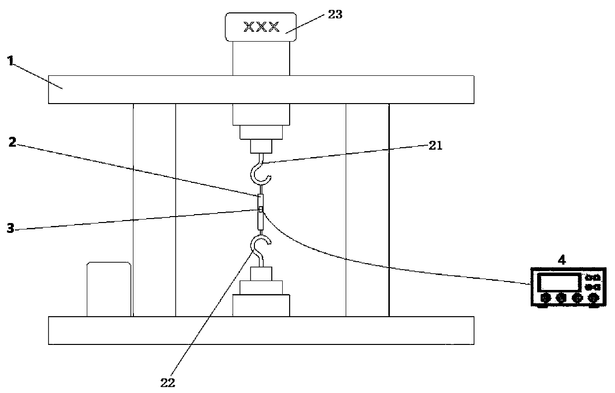
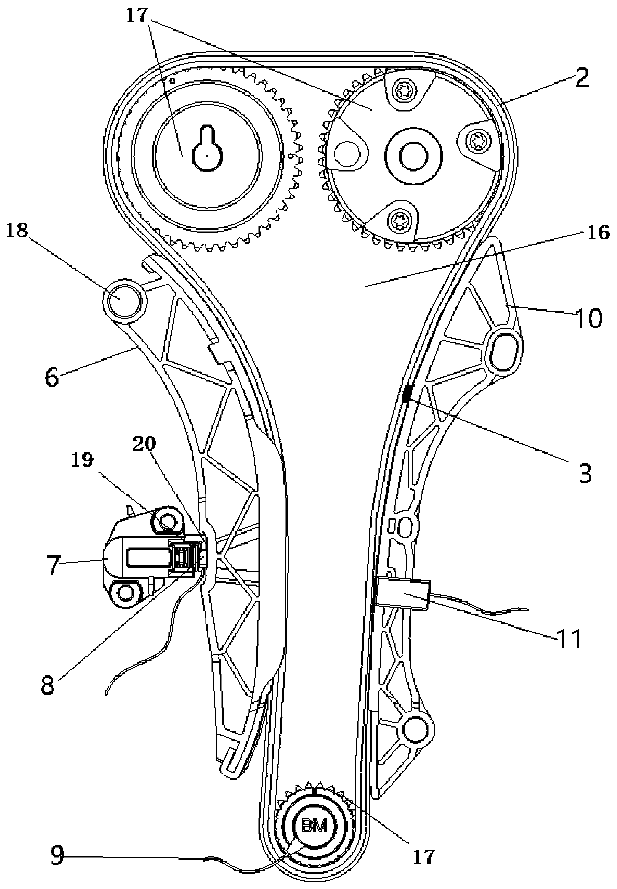
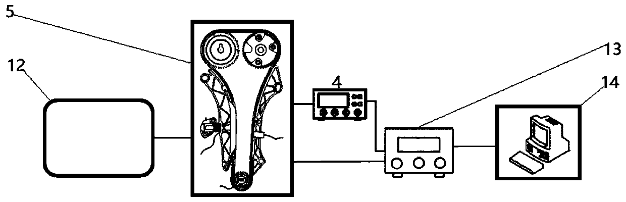
[0042] Such as figure 1 , 2 Shown in and 3, a kind of engine timing chain tension testing device comprises:

[0043] The engine 5 has a timing system, and the timing system includes a frame 16, a plurality of sprockets 17 that are rotatably mounted on the frame 16 and a timing chain 2 that is used to wind around each sprocket 17, and the timing system also It includes a fixed rail 10 fixed on the frame 16, a moving rail 6 rotatably mounted on the frame 16, and a tensioner 7 matched with the moving rail 6. The fixed rail 10 and the moving rail 6 are both arranged on the timing chain 2. The outer side is used to contact and cooperate with the timing chain 2;

[0044] The strain gauge 3 is used to be attached to the timing chain 2;

[0045] A dynamic strain gauge 4 is electrically connected to the strain gauge 3;

[0046] Tensile test stand 1 is used to cooperate with ...


PUM


Abstract

The invention discloses an engine timing chain tension testing device and method. The test device comprises an engine which comprises a rack, a plurality of chain wheels and a timing chain, and also comprises a fixed rail and a movable rail which are fixed on the rack; a strain foil which is used for being attached to the timing chain; a dynamic strain gauge; a tension test board; a first force sensor which is mounted on one side, matched with the timing chain, of the movable rail, or mounted on one side, matched with a tensioner, of the movable rail; a second force sensor which is mounted onone side, matched with the timing chain, of the fixed rail; a data acquisition system which is electrically connected with the dynamic strain gauge, the first force sensor and the second force sensor;a data storage computer which is electrically connected with the data acquisition system; and an engine endurance test bench. The engine timing chain tension testing device can actually measure the stress condition of the second timing chain of the engine under different rotating speed working conditions and different load working conditions.

Description

technical field [0001] The invention relates to testing equipment, in particular to an engine timing chain tension testing device and method. Background technique [0002] For the engine trial development test, there is a single test for the timing chain, and a tensile strength test to evaluate its strength and fatigue limit. At present, the evaluation of the force of the engine timing chain mainly relies on the CAE calculation method to evaluate the force of the chain during the actual engine operation. Since the dynamic calculation model of the timing system is relatively complicated, it is directly related to the polygonal benefit of the actual operation of the timing chain. The model There are many simplifications, so its accuracy is greatly reduced, and it cannot reach the actual reference value. Contents of the invention [0003] Aiming at the above problems, the present invention proposes an engine timing chain tension testing device and method. [0004] The techn...

Claims


Application Information

Patent Timeline
Patent Type & Authority Applications(China)
IPC IPC(8): G01M13/023G01M13/026G01M15/02G01L1/22G01L25/00
CPCG01L1/22G01L25/00G01M13/023G01M13/026G01M15/02
Inventor 白云龙丁佳陈江
Owner 矩阵汽车有限公司
Why Eureka
Try Eureka