
Fluid filter and method of using same

A fluid filter and filter element technology, applied in the direction of membrane filters, cartridge filters, chemical instruments and methods, etc., can solve the problems of oil spillage, difficulty in ensuring the sealing of the discharge passage for a long time, complicated insertion operations, etc. Achieves the effects of suppressing wear, reliable locking, and improving workability

Inactive Publication Date: 2007-07-04
TOYOTA BOSHOKU KK
View PDF2 Cites 7 Cited by
  • Summary
  • Abstract
  • Description
  • Claims
  • Application Information

AI Technical Summary

Problems solved by technology

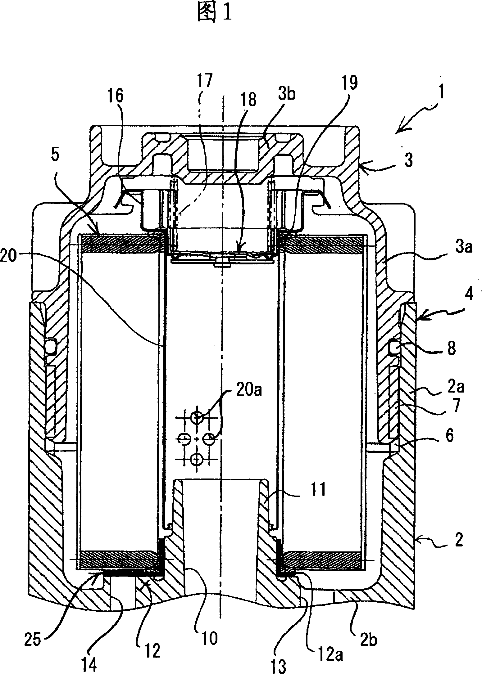
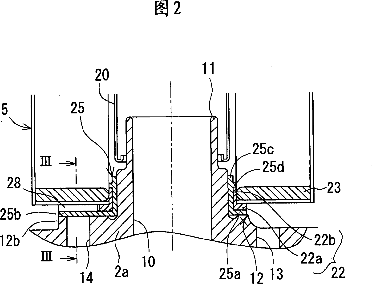
[0008] In addition, in the embodiment 1 of the above-mentioned patent document 2, since the protrusion 12 is inserted and pulled out with respect to the discharge passage, when the cover 1 is fastened to the base 2, it is necessary to use the operator's manual work to disengage the protrusion 12. Guide to the opening of the discharge passage and insert, this insertion work becomes very troublesome
In addition, since the cover 1 is loosened relative to the base 2 to completely release its combination, after that, the cover is lifted to disengage the protrusion 12 from the discharge passage, and the oil discharge starts, so the start time of the oil discharge is between the case and the cover. After the combination is released, there is a problem that there is a risk of oil spillage
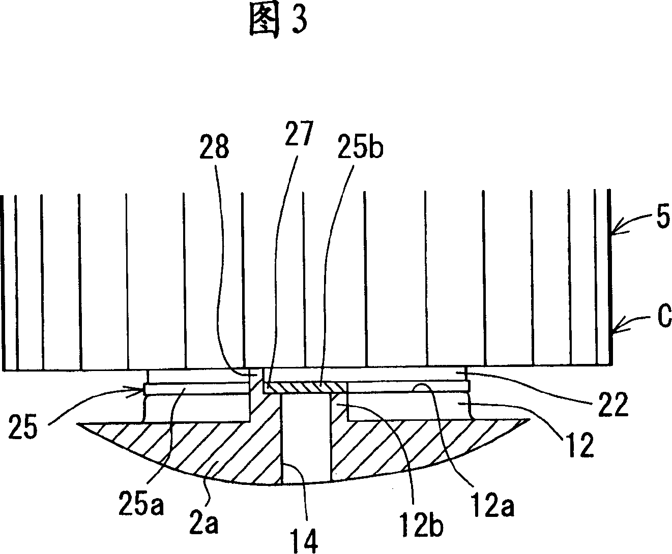
[0009] In addition, in Examples 2 and 3 of the above-mentioned Patent Document 2, the sealing members (O rings 53, 54 and check valve 39) are press-fitted to the surface of the base 2 to seal the discharge passage. When fastened to the base 2, the filter element 4 rotates together with the cover 1, and the sealing member slides on the surface of the housing. Due to the wear of the sealing member, it is difficult to ensure the sealing of the discharge passage for a long time in normal use. Danger

Method used


Image

  • Fluid filter and method of using same
  • Fluid filter and method of using same
  • Fluid filter and method of using same

Examples


Embodiment Construction

[0046] 1. Fluid filter

[0047] According to the fluid filter of the present embodiment, a case, a cover, a loading mechanism, a sealing member, and a rotation restricting mechanism are provided below. The fluid filter can be further equipped with a support body which will be described later, for example.

[0048] The above-mentioned "casing" only needs to form an inflow path, an outflow path, and a discharge path, and its structure, shape, material, etc. are not particularly limited. The case may have, for example, a bottomed cylindrical shape with an open top.

[0049] In the bottom of the above-mentioned housing, for example, an inflow passage is formed, and a discharge passage is formed in a protruding portion thicker than the bottom of the housing, and the opening of the discharge passage is at a position higher than the opening of the inflow passage. The passage and the inflow passage may be arranged on the same circumference. Thereby, the casing can be miniaturized. ...


PUM


Abstract

A fluid filter includes a case in which an inflow path, an outflow path, and a drainage path are formed, a cap which is engaged with the case through axial rotation, a biasing means (a coil spring) which biases a filter element housed inside a casing constituted by the case and the cap toward the case side, a rotation restricting means (an abutting portion and a projecting portion) which restricts rotation of the filter element in a fastening direction when the cap is rotated relative to the case in the fastening direction, and a sealing member provided on an axial end surface side of the filter element, which seals the drainage path when the filter element is biased by the biasing means and rotation thereof is restricted by the rotation restricting means.

Description

technical field [0001] The present invention relates to a liquid filter and its method of use. More specifically, the object of the present invention is to provide a filter that can maintain the leak tightness of the discharge path for a long time during normal use, and at the same time, improve the filter element replacement. An operational, simple and inexpensive fluid filter for fluid discharge and method of use thereof. Background technique [0002] As an oil filter of the prior art, it is known to accommodate a filter element in a substantially vertically elongated housing composed of a housing and a cover that can be coupled to each other by rotation, and to loosen the cover from the housing when replacing the filter element. At the time, the oil is discharged to the inside from the discharge passage provided in the casing (for example, refer to Patent Documents 1 and 2). [0003] In the above-mentioned Patent Document 1, it is disclosed that in the discharge passage ...

Claims


Application Information

Patent Timeline
Patent Type & Authority Applications(China)
IPC IPC(8): B01D27/08B01D35/02B01D35/30F01M11/03
CPCB01D35/147B01D2201/4076B01D2201/291B01D35/153B01D35/16
Inventor 名和辉好竹内智彦高原敏广
Owner TOYOTA BOSHOKU KK
Learn More