Mounting structure for external connector

A mounting structure and connector technology, applied in the electronic field, can solve the problems that the mounting structure is difficult to meet the product design requirements, the internal cables cannot be fixed, and the cable assembly and welding operation is affected, so as to avoid obstacles, improve efficiency, and reduce cables The hidden effect of wear

Pending Publication Date: 2020-01-14
HUNAN AEROSPACE ELECTROMECHANICAL EQUIP & SPECIAL MATERIAL INST
View PDF0 Cites 0 Cited by
  • Summary
  • Abstract
  • Description
  • Claims
  • Application Information

AI Technical Summary

Problems solved by technology

In the past, the installation structure of the external connector of the product was that the connector was fixed from the outside of the product to the upper cover of the product, and the connecting cable on the connector needed to pass through the upper cover of the product to connect with the components inside the product, and a long cable needed to be reserved. Occupies a large internal space; in addition, the mounting plate used to fix the external connector will affect the cable assembly and welding operation, and the internal cable cannot be fixed after the product is sealed, making the original installation structure difficult to meet the design requirements of the product

Method used


Image

  • Mounting structure for external connector
  • Mounting structure for external connector
  • Mounting structure for external connector

Examples


Embodiment Construction

[0016] The present invention will be further described below in conjunction with the accompanying drawings and embodiments.

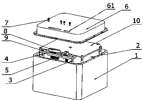
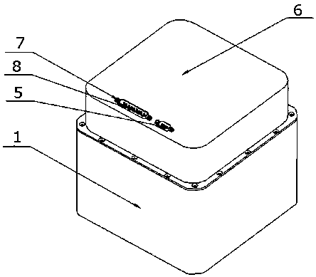
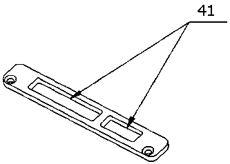
[0017] Such as Figure 1~3 As shown, an installation structure of an external connector includes a base 1 and an upper cover 6 of the product, a first printed board 2 installed on the base, and a support plate arranged between the base 1 and the first printed board 2 4. The support plate 4 is provided with a first through hole 41 for placing the connector, and the upper cover 6 is provided with a second through hole 61 corresponding to the first through hole 41 .

[0018] Through the above setting, the connector can be vertically placed on the support plate 4 through the first through hole 41, so that the cables on the connector can be directly welded downward to the first printed board 2. During the soldering process, The support plate 4 plays the role of fixing the connector and its own cable, preventing the connector from shaking and avoiding the ca...


PUM


Abstract

A mounting structure for an external connector includes a base, a first printed board mounted on the base, and an upper cover covering the first printed board. A support plate is arranged between thefirst printed board and the upper cover, and is provided with a first through hole. The upper cover is provided with a second through hole corresponding to the first through hole. In the present invention, A connector vertically passes through the first through hole to be placed on the support plate such that a cable on the connector can be directly soldered downward to the first printed board. During the assembly and soldering process, the support plate has an effect of fixing the connector and the cable, prevents the connector from shaking and avoids an excessively long cable. After the assembly and soldering, the upper cover is installed so that the connector can be connected to the outside through the second through hole.

Description

technical field [0001] The invention relates to the field of electronic technology, in particular to an installation structure of an external connector. Background technique [0002] With the development of the electronic assembly technology of the whole machine, the electronic assembly of the whole machine is required to be fast, efficient and simple. In the past, the installation structure of the external connector of the product was that the connector was fixed from the outside of the product to the upper cover of the product, and the connecting cable on the connector needed to pass through the upper cover of the product to connect with the components inside the product, and a long cable needed to be reserved. Occupies a large internal space; in addition, the mounting plate used to fix the external connector will affect the cable assembly and welding operation, and the internal cable cannot be fixed after the product is sealed, making the original installation structure d...

Claims


Application Information

Patent Timeline
Patent Type & Authority Applications(China)
IPC IPC(8): H01R12/51
CPCH01R12/515
Inventor 刘凡兵刘兆梅梁仁仁刘忠
Owner HUNAN AEROSPACE ELECTROMECHANICAL EQUIP & SPECIAL MATERIAL INST
Why Eureka
Try Eureka