Integrated SMC composite material ladder-type cable bridge

A cable bridge and composite material technology, applied to electrical components and other directions, can solve the problems of inconvenient installation and disassembly, inconvenient installation and disassembly, and difficulty in assembling the bridge, and achieve the advantages of convenient disassembly, improved stability, and improved convenience. Effect

Inactive Publication Date: 2020-01-14
镇江昌达电气有限公司
View PDF1 Cites 2 Cited by
  • Summary
  • Abstract
  • Description
  • Claims
  • Application Information

AI Technical Summary

Problems solved by technology

[0003] The existing ladder-type cable tray is integrally formed. Although the manufacturing cost is low, the assembly between the cable trays is relatively difficult, and the installation and disassembly are not very convenient.
[0004] Chinese patent document (publication number: CN109545626A) discloses a stepped cable tray, including a trapezoidal bottom plate and a trapezoidal cover, characterized in that: the upper and lower horizontal plates of the trapezoidal bottom plate are provided with through grooves, the trapezoidal The vertical plate of the base plate is provided with two upper and lower opposite cable fixing blocks, and the cable fixing blocks are provided with wire holes, and a reinforcing rib is provided between the vertical plate and the upper horizontal plate of the trapezoidal bottom plate. The front and rear sides of the trapezoidal bottom plate are connected with trapezoidal side plates, the left and right sides of the trapezoidal side plates are connected with connecting ears, the middle parts of the connecting ears are provided with through holes, and the upper and lower sides of the trapezoidal side plates There are buckles on both sides of the upper end of the outer side of the horizontal plate; although the ladder cable tray has a bridge corner protection structure, it is difficult to assemble between the bridges, and it is not very convenient to install and disassemble.

Method used


Image

  • Integrated SMC composite material ladder-type cable bridge
  • Integrated SMC composite material ladder-type cable bridge
  • Integrated SMC composite material ladder-type cable bridge

Examples


Embodiment Construction

[0027] The following will clearly and completely describe the technical solutions in the embodiments of the present invention with reference to the accompanying drawings in the embodiments of the present invention. Obviously, the described embodiments are only some, not all, embodiments of the present invention. Based on the embodiments of the present invention, all other embodiments obtained by persons of ordinary skill in the art without making creative efforts belong to the protection scope of the present invention.

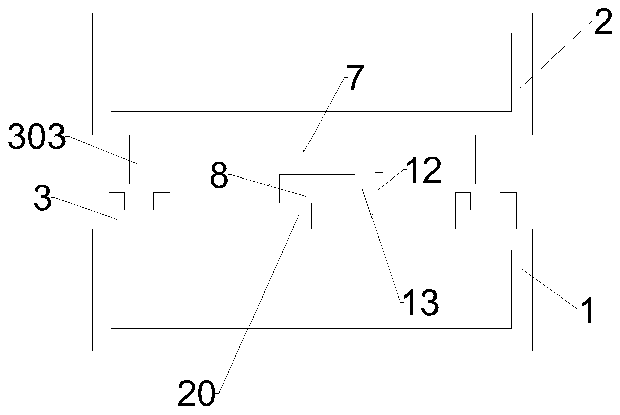
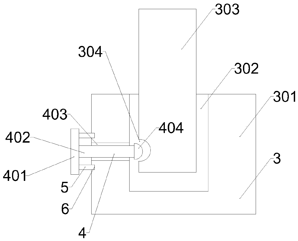
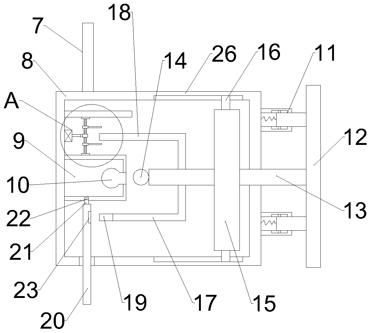
[0028] see Figure 1-3 , in the present invention, an integrally formed SMC composite material ladder cable tray includes a first cable tray 1 and a second cable tray 2, and the first cable tray 1 is symmetrically provided with two installation mechanisms 3, and the installation Mechanism 3 comprises installation block 301, and installation block 301 is provided with installation groove 302, and installation rod 303 is movable in installation groove 302, and d...


PUM


Abstract

The invention discloses an integrally formed SMC composite material ladder-type cable bridge. The cable bridge comprises a first cable bridge and a second cable bridge, and two mounting mechanisms aresymmetrically arranged on the first cable bridge; each mounting mechanism comprises a mounting block, and a mounting groove is formed in each mounting block, wherein a mounting rod is movably arranged in each mounting groove; the mounting rods and the second cable bridge are integrally formed, fixing grooves are formed in the bottoms of the mounting rods, and the fixing grooves and the fixing mechanisms are arranged in a clamped mode. The mounting rods are inserted into the mounting grooves, the fixing grooves are formed in the bottoms of the mounting rods, and fixed plates are moved to one side of the fixing grooves; a fixing cap is connected with the fixing grooves in a clamped mode, thereby achieving the preliminary fixing; finally, the fixed plates are limited through the limiting blocks and the limiting grooves, thereby improving the mounting stability.

Description

technical field [0001] The invention relates to the technical field of cable trays, in particular to an integrally formed SMC composite material ladder cable tray. Background technique [0002] The unique properties of SMC composite materials solve the shortcomings of wooden, steel and plastic meter boxes that are easy to age, corrode, poor insulation, poor cold resistance, poor flame retardancy, and short life. The excellent performance of composite meter boxes has absolute sealing and waterproof Performance, anti-corrosion performance, anti-theft performance, no need for grounding wires, beautiful appearance, safety protection with locks and lead seals, long service life, composite cable brackets, cable trench brackets, composite meter boxes, etc. are widely used in rural power grids, It is used in the transformation of urban network, and the cable tray is divided into trough type, tray type, ladder frame type, grid type and other structures; it is composed of brackets, su...

Claims


Application Information

Patent Timeline
Patent Type & Authority Applications(China)
IPC IPC(8): H02G3/04
CPCH02G3/0406H02G3/0487
Inventor 郭力嘉
Owner 镇江昌达电气有限公司
Why Eureka
Try Eureka