
Optical fiber head assembly with collimating focal length adjusting mechanism

An optical fiber head and component technology, applied in the field of laser cutting, can solve the problems of large waste of resources, low yield rate and low product quality, and achieve the effects of improving production efficiency, high surface quality and firm connection

Active Publication Date: 2017-10-24
DONGGUAN GLORYSTAR LASER TECH
View PDF7 Cites 0 Cited by
  • Summary
  • Abstract
  • Description
  • Claims
  • Application Information

AI Technical Summary

Problems solved by technology

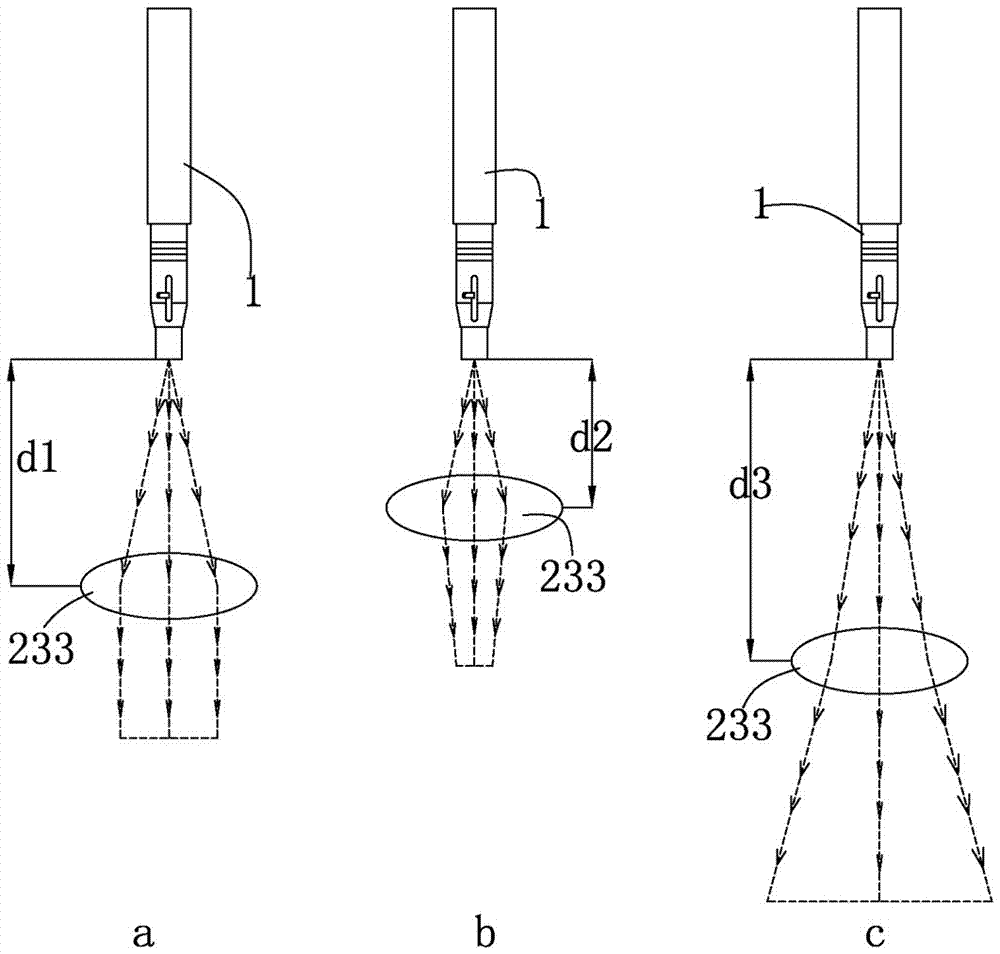
In actual use, if the light spots output from the optical fiber head and the collimated lens are not parallel, the cross-section quality will not be greatly affected when cutting thin plates, but when cutting thick plates, if the collimated light spots are not parallel, it will affect the cutting The impact on the surface quality of the fiber laser cutting machine is very obvious, that is, if the collimated light spots are not parallel, the quality of the products cut by the fiber laser cutting machine will be low, the yield rate will be low, and the waste of resources will be great.

Method used


Image

  • Optical fiber head assembly with collimating focal length adjusting mechanism
  • Optical fiber head assembly with collimating focal length adjusting mechanism
  • Optical fiber head assembly with collimating focal length adjusting mechanism

Examples


Embodiment Construction

[0031] The present invention will be described in further detail below in conjunction with the accompanying drawings.

[0032]The embodiments described by referring to the figures are exemplary, and are intended to explain the present application and should not be construed as limiting the present application. In the description of the present application, it should be understood that the terms "center", "longitudinal", "transverse", "length", "width", "thickness", "upper", "lower", "front", " Orientation or position indicated by "back", "left", "right", "vertical", "horizontal", "top", "bottom", "inner", "outer", "clockwise", "counterclockwise", etc. The relationship is based on the orientation or positional relationship shown in the drawings, and is only for the convenience of describing the present application and simplifying the description, rather than indicating or implying that the referred device or element must have a specific orientation, be constructed and operated ...


PUM


Abstract

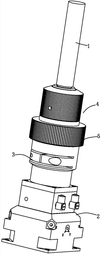
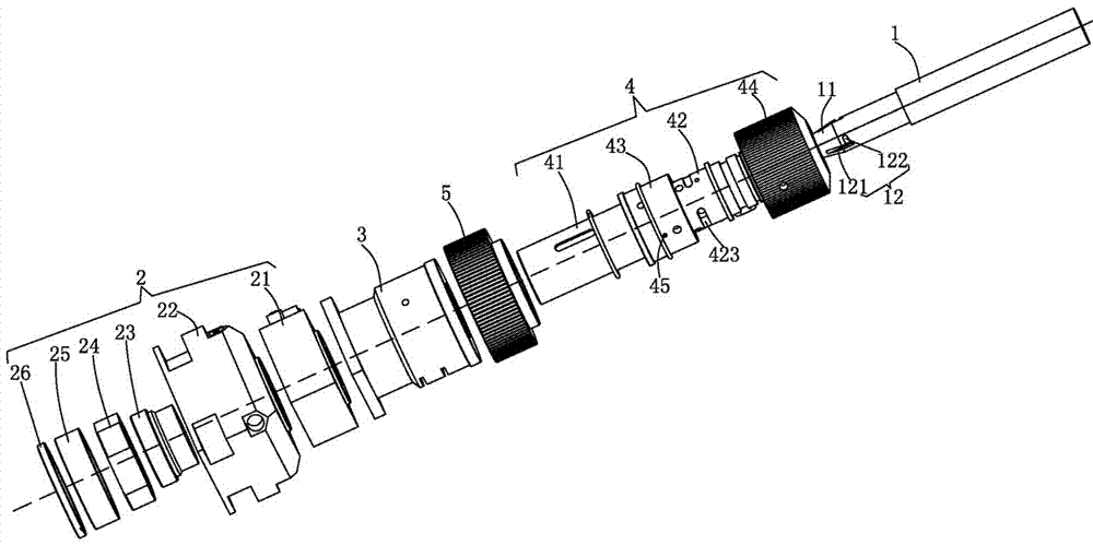
The invention discloses an optical fiber head assembly with a collimating focal length adjusting mechanism. The optical fiber head assembly comprises an optical fiber head and a collimating focusing assembly. A fixed locking cylinder is arranged at the upper end of the collimating focusing assembly, a locking positioning mechanism used for rapidly positioning and locking / dismounting and mounting of the optical fiber head is arranged on the fixed locking cylinder, the optical fiber head is vertically inserted in the locking positioning mechanism and is rapidly positioned and locked by the mechanism, and the fixed locking cylinder and the locking positioning mechanism are internally provided with a light channel for emitting of optical fiber head light; a collimating focusing rotary knob is further arranged at the position, matched with the inserting end of the optical fiber head, of the fixed locking cylinder and is in screw joint with the fixed locking cylinder, the upper end face of the collimating focusing rotary knob is in abutting contact with the locking positioning mechanism, the collimating focusing rotary knob drives the locking positioning mechanism and the optical fiber head to axially move, the collimating focusing assembly is placed on the matched collimating focal point, and the optical fiber head emits light along the light channel, is subject to collimating through the collimating focusing assembly on the collimating focus point and then outputs parallel light. The focal length of the optical fiber head of the optical fiber head assembly is adjustable relative to the collimating focusing assembly, and the optical fiber head is inserted and locked rapidly.

Description

technical field [0001] The invention relates to the technical field of laser cutting, in particular to an optical fiber head assembly with an adjustable collimation focal length mechanism. Background technique [0002] In recent years, the domestic demand for laser cutting machine tools has increased rapidly. Fiber laser cutting machine tools have many advantages such as easy maintenance, low consumption cost, and excellent cutting section, so the growth in demand is particularly prominent. As an important component of the fiber laser cutting machine, the fiber laser cutting head directly affects the cutting quality of the fiber laser cutting machine. [0003] The optical fiber cutting heads currently on the market do not have an adjustable collimation focal length. Although the size of the focal length of the collimating lens can be calculated very accurately when designing the fiber cutting head, and then the collimating focus assembly is cured, so that the output light o...

Claims


Application Information

Patent Timeline
Patent Type & Authority Applications(China)
IPC IPC(8): B23K26/064G02B7/04
CPCG02B7/04B23K26/064
Inventor 姚玉东尹怀化何忠宝郝英锋李荣飞刘南麟
Owner DONGGUAN GLORYSTAR LASER TECH
Learn More