Device and cutting method for semi-automatic cutting of product waste

A semi-automatic, scrap technology, applied in the direction of positioning device, feeding device, clamping, etc., can solve the problems of taking up large production time, uneconomical, and different lengths, and achieve the effect of avoiding misoperation

Active Publication Date: 2020-01-17
JIANGXI KAILIDE TECH CO LTD
View PDF12 Cites 0 Cited by
  • Summary
  • Abstract
  • Description
  • Claims
  • Application Information

AI Technical Summary

Problems solved by technology

[0002] In the production process of the manufacturing industry, it is inevitable that there will be a surplus of processing materials in each process. There are a large number of them that can be used as raw materials for other processes. The fixing during cutting needs enough adjustment space
[0003] At present, one solution to the cutting of waste is to cut the waste on a lathe. When manual cutting is used, the labor cost is too large, but cutting with a digital lathe takes up a lot of production time and is uneconomical.

Method used


Image

  • Device and cutting method for semi-automatic cutting of product waste
  • Device and cutting method for semi-automatic cutting of product waste
  • Device and cutting method for semi-automatic cutting of product waste

Examples


Embodiment Construction

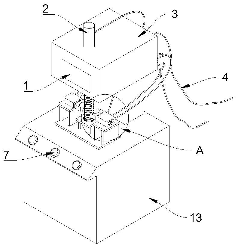
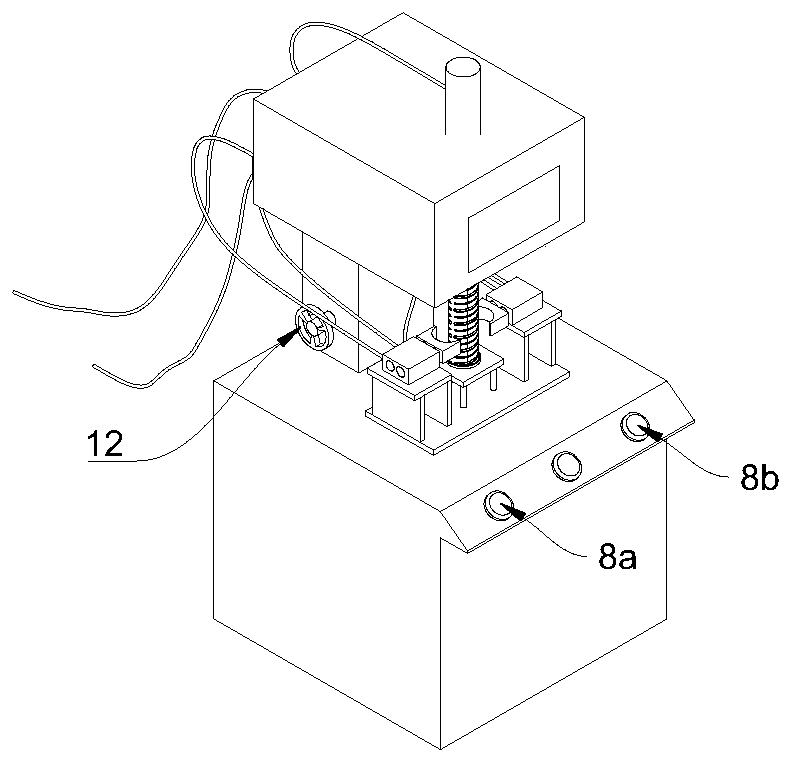
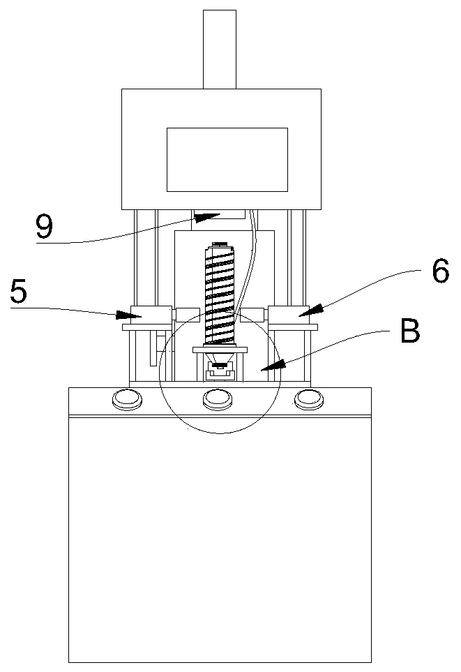
[0024] next combined with Figure 1~5 A specific embodiment of the present invention is described in detail.

[0025] A semi-automatic device for cutting product waste, including a touch screen 1, an oil cylinder 2, a chassis 3, an air pipe 4, a right auxiliary clamp 5, a left auxiliary clamp 6, an emergency stop button 7, an action button 8, a driving head 9, and a lifting mechanism 10 , cutting knife 11, lifting disc 12, fixed platform 13, lower auxiliary clip 14 and fixed frame 15; described cabinet 3 is connected on the fixed platform 13 by elevating mechanism 10, and elevating mechanism 10 is carried out by the elevating plate 12 that its side is provided with Lifting adjustment, described lifting mechanism is prior art, and the inventive point of the present invention does not lie in this, so do not elaborate.

[0026] The cabinet 3 is the control component of the present invention, with a built-in control module and pneumatic pipelines. The side of the cabinet 3 facing...


PUM


Abstract

The invention provides a device for semi-automatic cutting of product waste. The device comprises a touch display screen, an oil cylinder, a case, air pipes, a right auxiliary clamp, a left auxiliaryclamp, emergency stop buttons, action buttons, a driving head, a lifting mechanism, a cutter knife, a lifting disc, a fixed station, a lower auxiliary clamp and a fixed bracket; the case is connectedonto the fixed station through the lifting mechanism, and the lifting mechanism comprises the lifting disc arranged at the side part; a built-in control module and a pneumatic pipeline are arranged inthe case, the touch display screen electrically connected with the built-in control module is arranged on the case, the driving head is arranged on the side facing the fixed station, the oil cylinderis arranged at the top of the case, and the driving head is connected with the oil cylinder and rotates under driving of the oil cylinder; and the fixed bracket is arranged on the fixed station, thefixed center of the fixed bracket is located in the central axis of the driving head, the lower auxiliary clamp is arranged on the fixed station, and the cutter knife is fixedly connected onto the fixed station. By means of the detachable lower auxiliary clamp, materials with different diameters are clamped, the device is semi-automatic and is calibrated manually, meanwhile, the device can act under the action of logical AND when the two action buttons are pressed simultaneously to produce two signals, so that the condition of misoperation is avoided, the semi-automatic cutting is realized, the operation and control are simple, and the cutting efficiency is greatly increased.

Description

technical field [0001] The invention relates to the field of waste material cutting, in particular to a device for semi-automatically cutting product waste material. The invention also provides a semi-automatic cutting method for cutting product waste material, which can semi-automatically cut cylindrical waste material. Background technique [0002] In the production process of the manufacturing industry, it is inevitable that there will be a surplus of processing materials in each process. There are a large number of them that can be used as raw materials for other processes. The fixing during cutting needs enough adjustment space. [0003] At present, one solution to the cutting of waste is to cut the waste on a lathe. When manual cutting is used, the labor cost is too large, but cutting with a digital lathe takes up a lot of product production time, which is uneconomical. Contents of the invention [0004] According to the problems raised by the background technology,...

Claims


Application Information

Patent Timeline
Patent Type & Authority Applications(China)
IPC IPC(8): B23D79/00B23Q3/12B23Q5/22B26D3/06B26D5/00B26D7/02
CPCB23D79/00B23Q3/12B23Q5/22B26D3/06B26D5/00B26D7/02B26D2007/013
Inventor 祝金军张一飞李忠溪何家冰
Owner JIANGXI KAILIDE TECH CO LTD
Why Eureka
Try Eureka