Different-axis rotary shearing energy-absorbing aero seat

A technology of rotary shearing and aviation, which is applied in the field of aviation passenger seats, can solve the problems of being unable to pass through, unable to produce energy-absorbing effects, passenger damage, etc., and achieve the effect of avoiding interference

Active Publication Date: 2020-01-17
湖北航宇嘉泰飞机设备有限公司
View PDF7 Cites 2 Cited by
  • Summary
  • Abstract
  • Description
  • Claims
  • Application Information

AI Technical Summary

Problems solved by technology

[0002] At present, an airline passenger seat includes a seat pan, a side plate, a backrest, a connecting plate, a shear ring and a driving mechanism, the side plate is fixed on the left or right side of the seat pan, and the backrest is arranged on the chair pan. On the rear side of the basin, one end of the connecting plate is hinged to the side plate, the other end of the connecting plate is hinged to the rotating shaft of the backrest, and the drive mechanism is used to drive the connecting plate to rotate relative to the side plate, thereby Drive the backrest to tilt forward or backward. This mechanism can realize the linkage between the chair pan and the backrest. The rotating shaft of the backrest and the shearing ring are coaxially arranged. The above-mentioned shearing ring will be cut off, so as to achieve the function of energy absorption protection, but there is a linkage design between the seat pan and the backrest, and the linkage structure will interfere with the turning of the backrest to a certain extent, so that the shearing ring is not easy to be cut off , can not produce energy absorption effect, will cause serious damage to passengers or fail to pass the HIC (Head Injury Criterion neck injury criterion) test

Method used


Image

  • Different-axis rotary shearing energy-absorbing aero seat
  • Different-axis rotary shearing energy-absorbing aero seat

Examples


Embodiment Construction

[0014] In order to make the object, technical solution and advantages of the present invention clearer, the present invention will be further described in detail below in conjunction with the accompanying drawings and embodiments. It should be understood that the specific embodiments described here are only used to explain the present invention, not to limit the present invention.

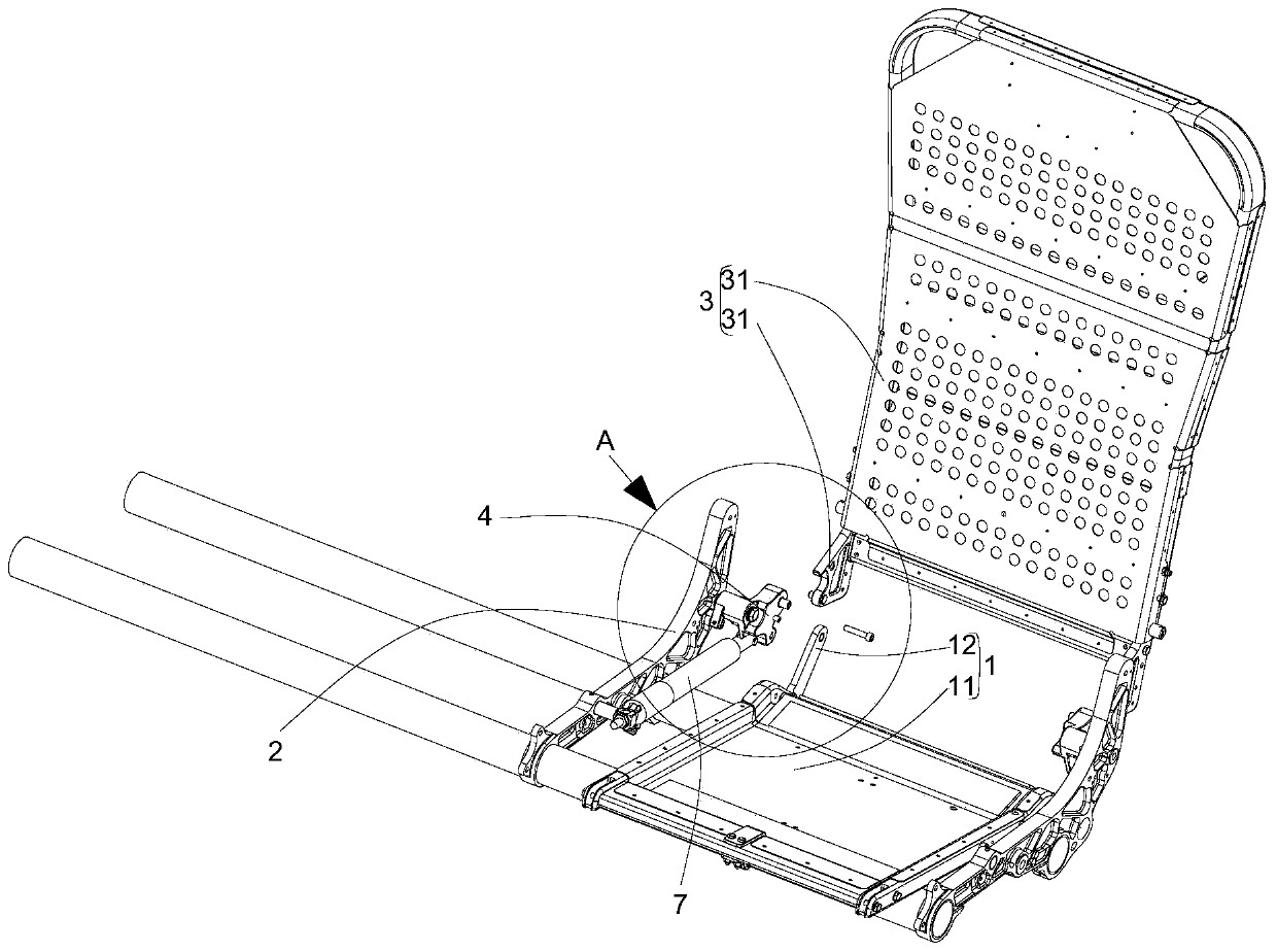
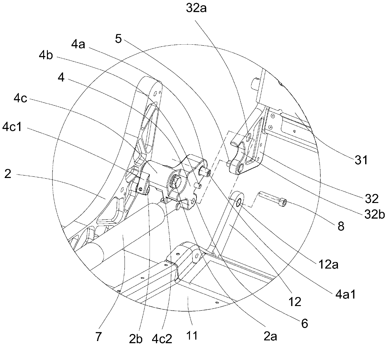
[0015] see figure 1 , figure 2 , the present embodiment provides an off-axis rotating shearing energy-absorbing aviation seat, comprising: a seat pan 1, a side panel 2, a backrest 3, a connecting plate 4, a shearing pin 5, a shearing ring 6 and a driving mechanism 7 ( figure 2 The dotted line drawn in is the assembly line).

[0016] The side plate 2 is fixed on the left or right side of the chair pan 1. In this embodiment, the side plate 2 is a fixed part, and the position and angle of the side plate 2 will not change. The basin 1, the backrest 3, and the connecting plate 4 all change in angle...


PUM


Abstract

The invention discloses a different-axis rotary shearing energy-absorbing aero seat which comprises a chair basin, a side plate, a backrest, a connecting plate, a shearing pin, a shearing ring and a driving mechanism. The side plate is fixed on the left side or the right side of the chair basin; the lower end of the backrest is hinged to the rear side of the chair basin, and the hinged axis of thebackrest and the chair basin is a first axis; the first end of the connecting plate is hinged to the side plate, the second end of the connecting plate is hinged to the backrest, the shearing ring isarranged at the third end of the connecting plate, and the hinged axis of the first end of the connecting plate and the side plate is a second axis; when the backrest bears large inertia and inclinesforwards, the backrest rotates relative to the side plate with the first axis as the rotating axis, in the process, the shearing ring is torn open by the shearing pin, the rotating axis of the backrest and the axis of the shearing ring are staggered through the structure, and meanwhile interference of a linkage structure on stress of the shearing ring is avoided.

Description

technical field [0001] The invention relates to the technical field of aviation passenger seats, in particular to an off-axis rotating and shearing energy-absorbing aviation seat. Background technique [0002] At present, an airline passenger seat includes a seat pan, a side plate, a backrest, a connecting plate, a shear ring and a driving mechanism, the side plate is fixed on the left or right side of the seat pan, and the backrest is arranged on the chair pan. On the rear side of the basin, one end of the connecting plate is hinged to the side plate, the other end of the connecting plate is hinged to the rotating shaft of the backrest, and the drive mechanism is used to drive the connecting plate to rotate relative to the side plate, thereby Drive the backrest to tilt forward or backward. This mechanism can realize the linkage between the chair pan and the backrest. The rotating shaft of the backrest and the shearing ring are coaxially arranged. The above-mentioned sheari...

Claims


Application Information

Patent Timeline
Patent Type & Authority Applications(China)
IPC IPC(8): B64D11/06
CPCB64D11/0619
Inventor 李端兵余能文
Owner 湖北航宇嘉泰飞机设备有限公司
Why Eureka
Try Eureka