Eureka AIR delivers breakthrough ideas for toughest innovation challenges, trusted by R&D personnel around the world.

Bridge expansion device

A telescopic device and bridge technology, which is applied in the direction of bridges, bridge parts, bridge construction, etc., can solve the problems of unfavorable repeated use, deformation and uplift of parts, large deformation, etc.

Inactive Publication Date: 2020-01-17
SICHUAN DEPT OF TRANSPORTATION HIGHWAY PLANNING PROSPECTING & DESIGN RES INST +1
View PDF12 Cites 3 Cited by
  • Summary
  • Abstract
  • Description
  • Claims
  • Application Information

AI Technical Summary

Problems solved by technology

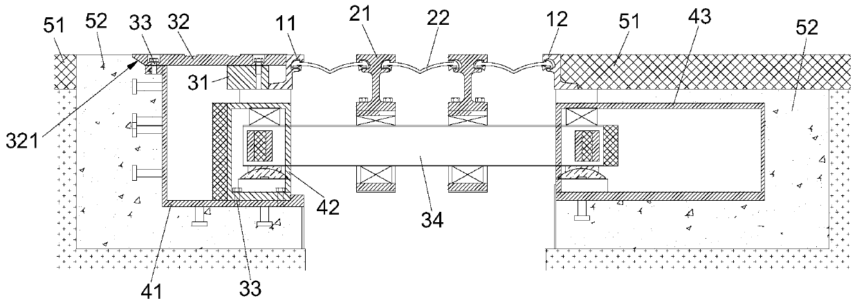
The patent No. ZL 200820039362.1 discloses a modular bridge expansion device. It can be seen from the figure that the side beams are welded to the displacement control box, and the middle beam is welded to the support beam. When an earthquake occurs, the deformation of the bridge expansion device The amount will be very large, and the device will be connected by welding and other methods, which will cause damage to the side beams, center beams, displacement control boxes and support beams, which is not conducive to repeated use, and the extrusion of parts will cause deformation and uplift, and the bridge ground will be damaged Seriously damaged

Method used


Image

  • Bridge expansion device
  • Bridge expansion device
  • Bridge expansion device

Examples


Embodiment Construction

[0023] In order to make the purpose, technical solutions and advantages of the embodiments of the present invention clearer, the technical solutions in the embodiments of the present invention will be clearly and completely described below in conjunction with the drawings in the embodiments of the present invention. Obviously, the described embodiments It is a part of embodiments of the present invention, but not all embodiments. The components of the embodiments of the invention generally described and illustrated in the figures herein may be arranged and designed in a variety of different configurations.

[0024] Accordingly, the following detailed description of the embodiments of the invention provided in the accompanying drawings is not intended to limit the scope of the claimed invention, but merely represents selected embodiments of the invention. Based on the embodiments of the present invention, all other embodiments obtained by persons of ordinary skill in the art wi...


PUM


Abstract

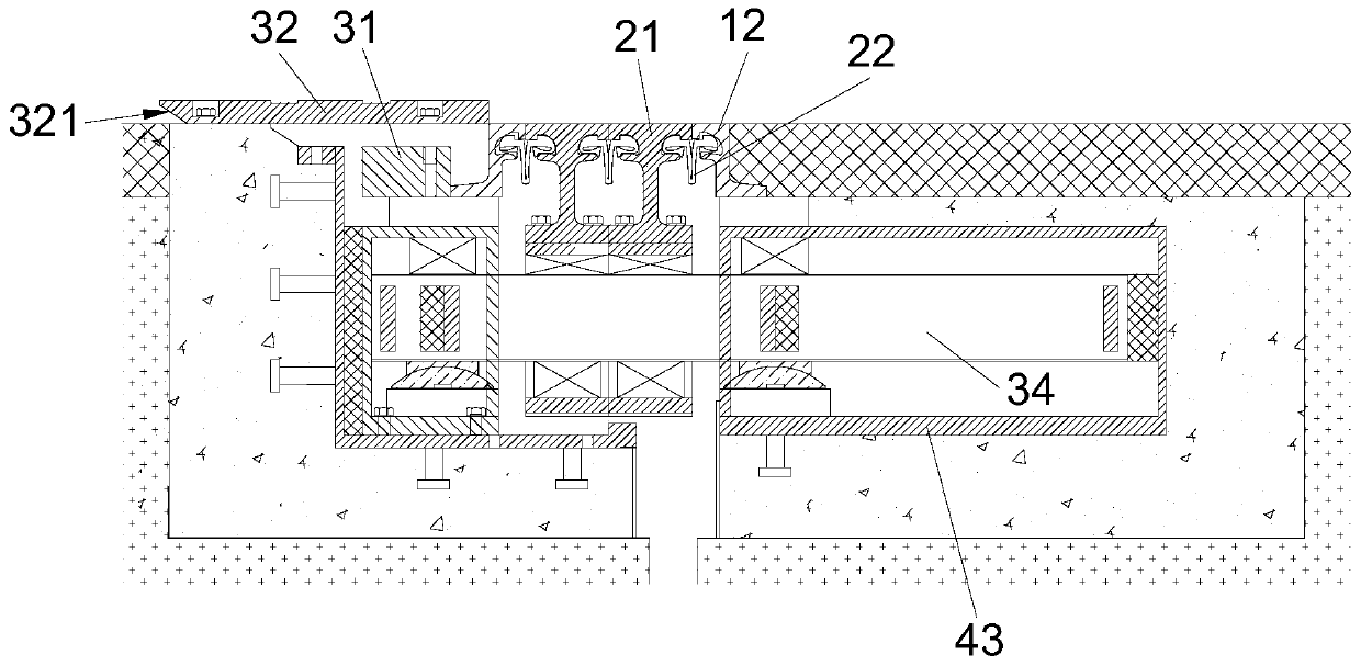
The invention discloses a bridge expansion device. The bridge expansion device comprises a first edge beam, a second edge beam, a connecting block and a cover plate, a middle beam assembly is arrangedbetween the first edge beam and the second edge beam, the middle beam assembly comprises a plurality of middle beams which are sequentially arranged between the first edge beam and the second edge beam in parallel, and sealing strips are arranged between the edge beams and the adjacent middle beams and between every two adjacent middle beams. The connecting block abuts against the side, away fromthe second edge beam, of the first edge beam. The cover plate abuts against the side, away from the second edge beam, of the first edge beam, the connecting block is located on the lower side of thecover plate, and the connecting block is connected with the cover plate through the shear connector. The supporting beam is used for supporting the middle beam. When an earthquake occurs, excessive parts can be prevented from being damaged.

Description

technical field [0001] The invention belongs to the technical field of bridge structures, and in particular relates to a bridge telescopic device. Background technique [0002] Bridge telescopic device refers to that in order to meet the requirements of bridge deck deformation, telescopic devices are usually installed between two girder ends, between the girder end and abutment, or at the hinged position of the bridge. The patent No. ZL 200820039362.1 discloses a modular bridge expansion device. It can be seen from the figure that the side beams are welded to the displacement control box, and the middle beam is welded to the support beam. When an earthquake occurs, the deformation of the bridge expansion device The amount will be very large, and the device will be connected by welding and other methods, which will cause damage to the side beams, center beams, displacement control boxes and support beams, which is not conducive to repeated use, and the extrusion of parts will...

Claims


Application Information

Patent Timeline
IPC IPC(8): E01D19/06
CPCE01D19/06E01D19/062
Inventor 孙浩蒋建军陈绍军宋开辉周海波李明生
Owner SICHUAN DEPT OF TRANSPORTATION HIGHWAY PLANNING PROSPECTING & DESIGN RES INST
Why Eureka
Eureka Blog
Learn More