Active oil-gas separator

An oil-gas separator, active technology, applied in the direction of engine components, machines/engines, mechanical equipment, etc., can solve the problems of insufficient oil-gas separation, poor separation effect, etc., and achieve good effect of oil-gas separation

Active Publication Date: 2020-01-17
SHENTONG TECH GRP CO LTD
View PDF6 Cites 9 Cited by
  • Summary
  • Abstract
  • Description
  • Claims
  • Application Information

AI Technical Summary

Problems solved by technology

[0005] The first purpose of the present invention is to provide an active oil-gas separator for sufficient oil-gas separation of crankcase blow-by gas in order to overcome the poor separation effect and insufficient oil-gas separation in the prior art

Method used


Image

  • Active oil-gas separator
  • Active oil-gas separator
  • Active oil-gas separator

Examples


Embodiment 1

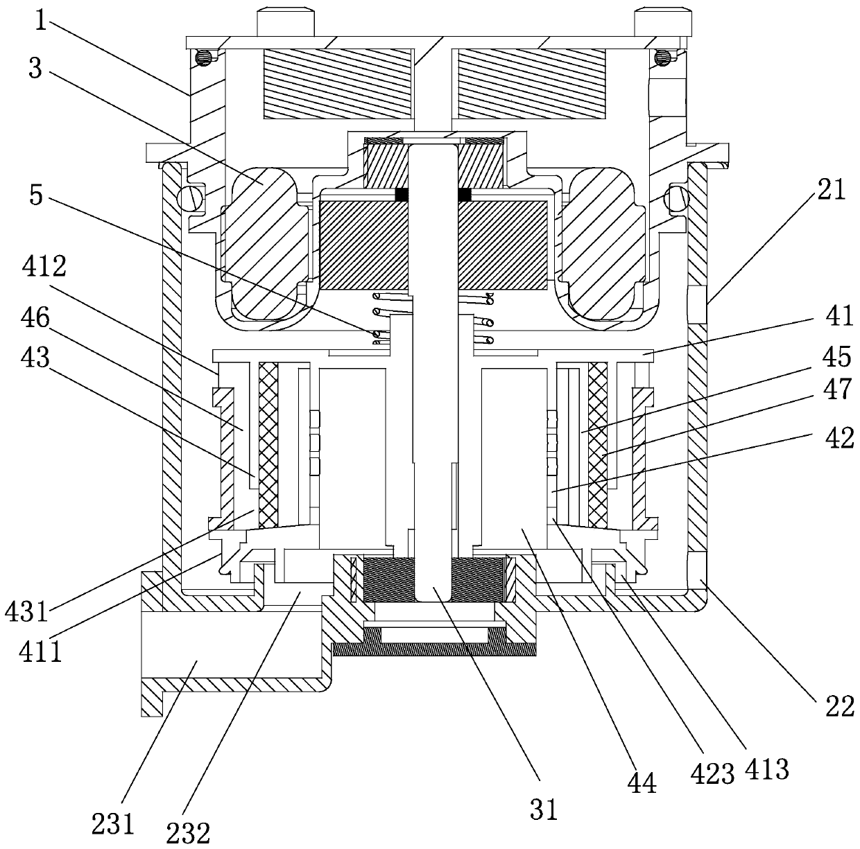
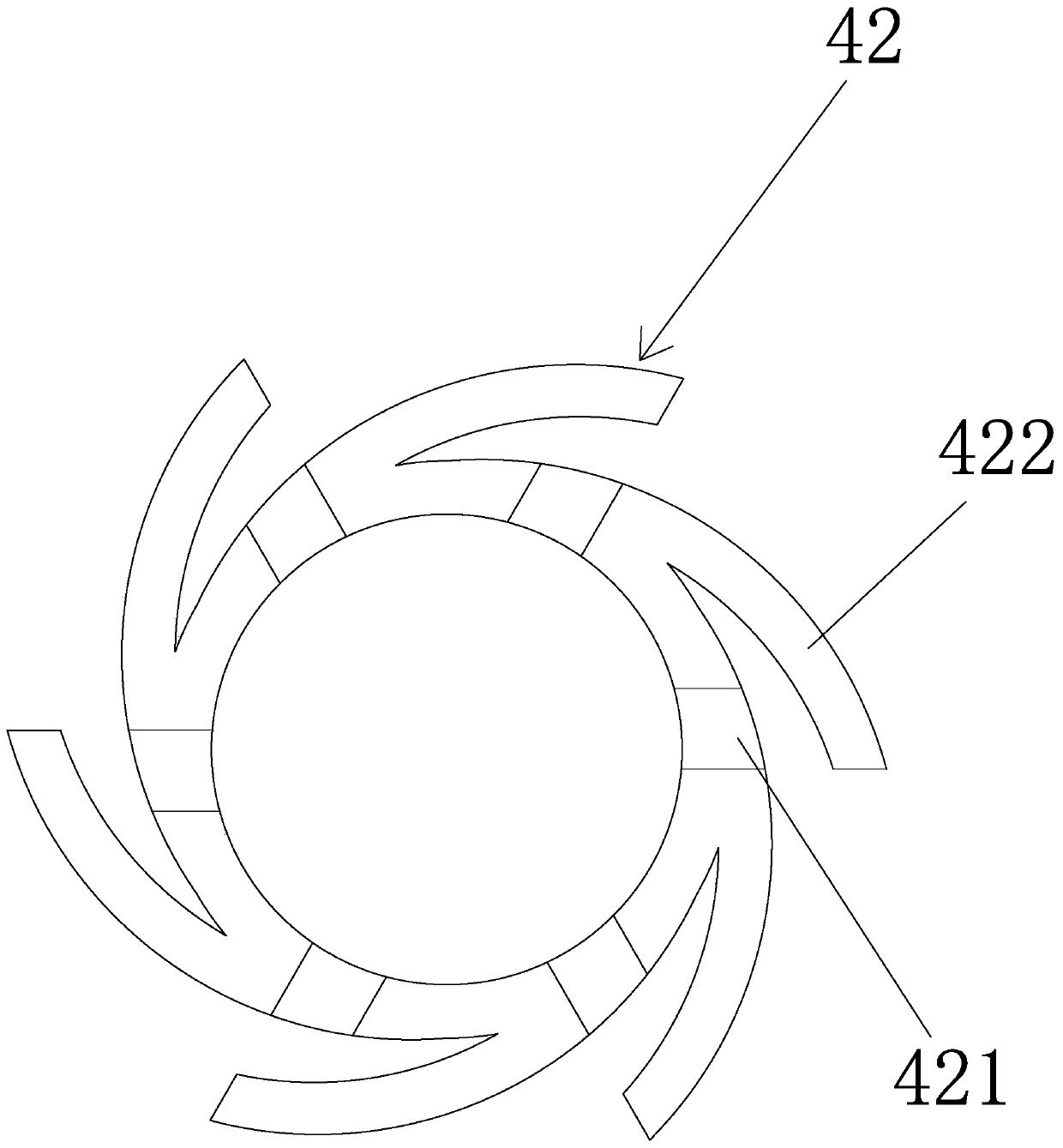
[0034] Embodiment 1: a kind of active oil-gas separator, such as Figure 1 to Figure 2 As shown, it includes an upper casing 1, a lower casing 2 provided with an exhaust port 21 and an oil discharge port 22, a motor 3 installed in the upper casing, and a separation device 4 fixedly connected to the output shaft 31 of the motor. The separation device Including the separation device housing 41, the separation device housing is provided with an air outlet 411 on its upper part and an oil outlet 412 on its lower part, and a first separator 42 with a vent hole is arranged inside the separation device housing from inside to outside And the second partition 43, the first partition and the second partition divide the inside of the separation device housing from inside to outside into the first chamber 44, the second chamber 45 and the third chamber 46, the first partition The lower end is provided with an oil discharge hole 423, the inner bottom surface of the separation device housin...

Embodiment 2

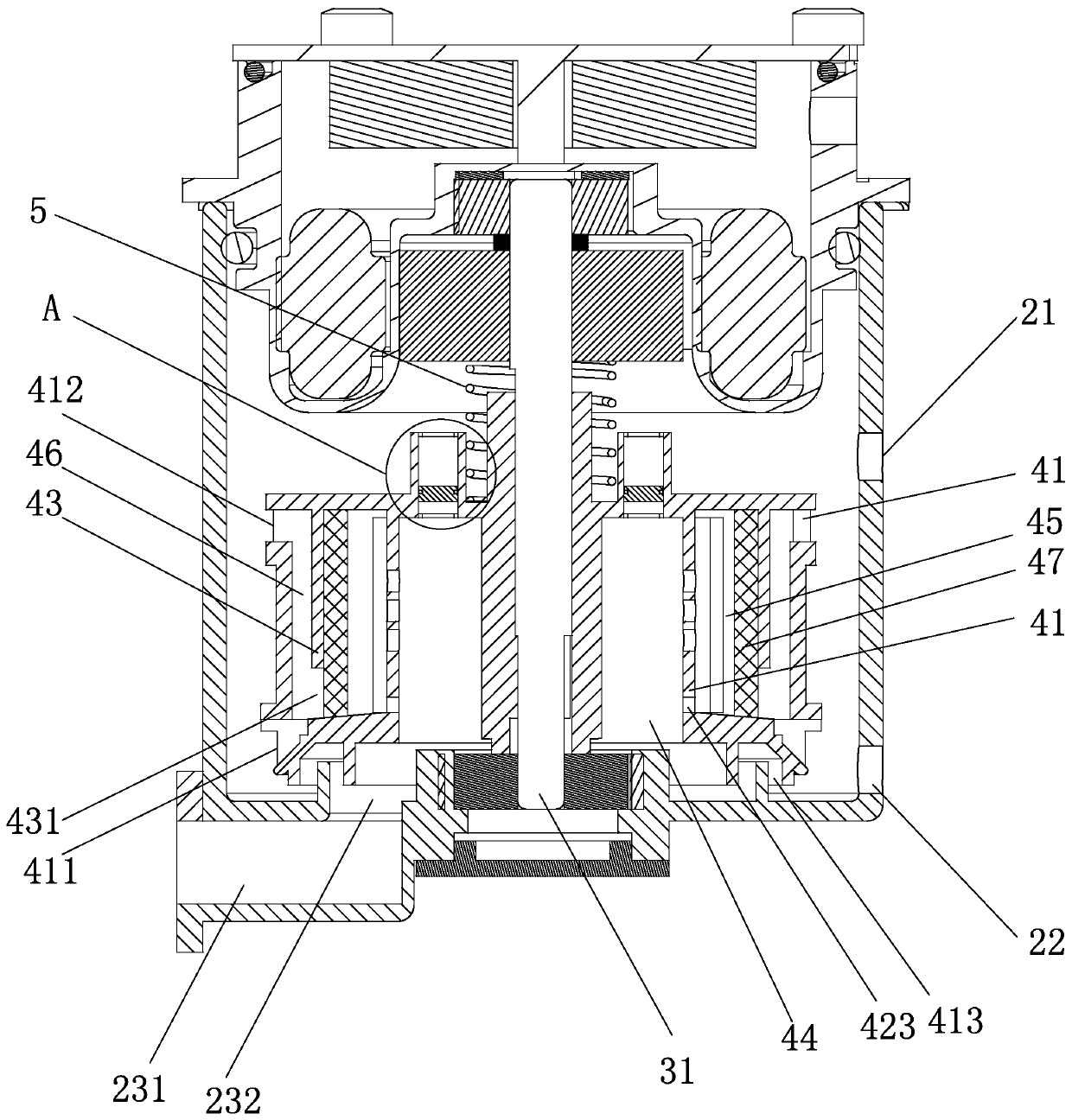
[0039] Embodiment 2, the remaining structure of this embodiment is with reference to embodiment 1, and its difference is:

[0040] Such as image 3 and Figure 4 As shown, above the first cavity is provided with an adjustment cavity 6 for adjusting the air pressure in the first cavity. When the air pressure in the first cavity is greater than the preset value, within the adjustment range of the adjustment cavity, the adjustment cavity and the second cavity The volume connected to the first cavity increases, and when the air pressure in the first cavity is lower than a preset value, the volume connected to the first cavity decreases within the adjustment range of the adjustment cavity.

[0041] Specifically, the adjustment chamber includes an adjustment chamber wall 62 formed by extending upward from the housing of the separation device, a floating adjustment plate 61 sliding up and down along the adjustment chamber wall, and a regulating valve for connecting the first chamber...


PUM


Abstract

The invention discloses an active oil-gas separator. The separator comprises an upper shell, a lower shell provided with an exhaust port and an oil discharge port, a motor mounted in the upper shell and a separation device fixedly connected to a motor output shaft, wherein the separation device comprises a separation device shell, the separation device shell is provided with an air outlet locatedat the upper part of the separation device shell and an oil outlet located at the lower part of the separation device shell, a first partition plate and a second partition plate are arranged in the separation device shell from inside to outside, the first partition plate and the second partition plate divide the interior of the separation device shell into a first cavity, a second cavity and a third cavity from inside to outside, the first cavity communicates with the second cavity through a vent hole, the bottom of the second partition plate is provided with an oil-gas pass port for communication between the second cavity and the third cavity, a filter element is arranged in the second cavity, the filter element is arranged close to the second partition plate, the oil outlet and the air outlet both communicate with the third cavity, and an air inlet channel communicating with the first cavity is formed in the lower shell.

Description

technical field [0001] The invention relates to the technical field of engine crankcase ventilation, in particular to an active oil-gas separator. Background technique [0002] The oil-air separator connects the crankcase of the engine with the intake manifold and the air filter. At present, almost all internal combustion engines work by inhaling the mixed gas, compressing it, and then igniting or compressing the mixed gas, so as to drive the piston to do work to generate power. Gas compression and combustion will generate high pressure, and the compressed gas will escape from the gap between the piston and the cylinder block, the gap between the piston ring and the cylinder block, and enter the crankcase to form crankcase blow-by gas. The main function of the oil separator: Before the blow-by gas is introduced into the combustion chamber for re-combustion, it is necessary to effectively separate the blow-by gas in the crankcase, so that as little oil as possible enters the ...

Claims


Application Information

Patent Timeline
IPC IPC(8): F01M13/04F01M13/02
CPCF01M13/021F01M13/04F01M2013/0422
Inventor 方立锋蔡炳芳饶聪超徐析斌
Owner SHENTONG TECH GRP CO LTD
Why Eureka
Try Eureka