Differential pressure adjusting device of residual mist recovery system and oil mist lubrication system

A technology of recovery system and adjustment device, applied in the direction of engine lubrication, lubricating parts, chemical instruments and methods, etc., can solve the problems such as the influence of the upstream engine pump lubrication, the destruction of the micro-positive pressure of the bearing box, and the large consumption of instrument air. Achieve the effect of good oil and gas separation and reduce maintenance workload

Pending Publication Date: 2019-07-16
徐少文
View PDF0 Cites 1 Cited by
  • Summary
  • Abstract
  • Description
  • Claims
  • Application Information

AI Technical Summary

Problems solved by technology

[0003] The problems in the existing technology include: 1. The negative pressure is too high, which affects the lubrication of the upstream machine pump. According to the user’s feedback, the negative pressure is too high, which increases the amount of oil mist required for the lubrication of the upstream machine pump by nearly 50%. The recovery line of each pump is equipped with a flow regulating valve, but it is still unavoidable that part of the oil mist exceeding the normal discharge volume is drawn from the bearing housing
Negative pressure is always maintained in the entire recovery pipeline, sometimes even destroying the micro-positive pressure in the bearing box, which is not allowed
[0004] 2. The instrument wind consumes a lot
Although the cost of instrument air in each factory is slightly different, the cost of instrument air consumed every year also needs hundreds of thousands of yuan
[0005] 3. The oil and gas separation effect is not good
So the separation effect is not ideal
[0006] 4. The filter element needs to be replaced regularly, which increases maintenance costs

Method used


Image

  • Differential pressure adjusting device of residual mist recovery system and oil mist lubrication system
  • Differential pressure adjusting device of residual mist recovery system and oil mist lubrication system
  • Differential pressure adjusting device of residual mist recovery system and oil mist lubrication system

Examples


Embodiment Construction

[0021] Through the following description of the embodiments, it will be more helpful for the public to understand the present invention, but the specific embodiments given by the applicant cannot and should not be regarded as limitations on the technical solutions of the present invention, any components or technical features Changes to the definition and / or formal but not substantive changes to the overall structure should be regarded as the scope of protection defined by the technical solutions of the present invention.

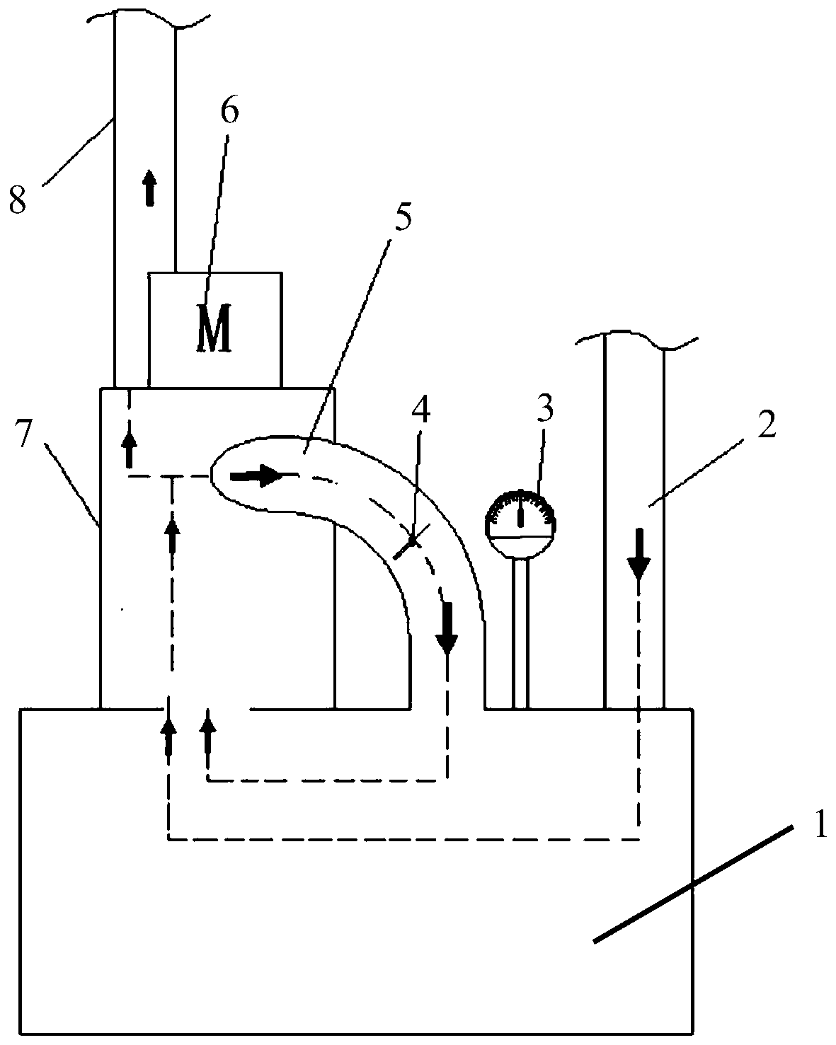
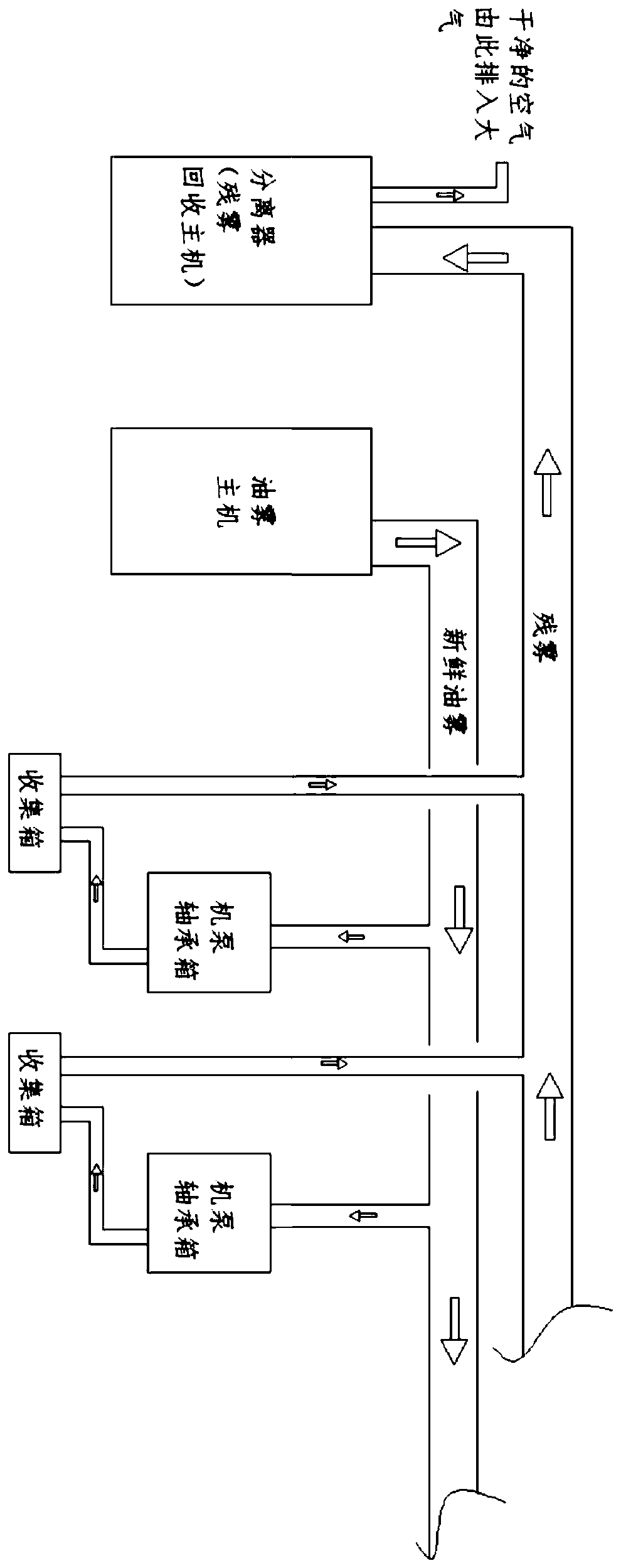
[0022] Such as Figure 1 to Figure 2 As shown, the oil mist lubrication system: the lubricating oil is atomized into oil mist (aerosol mixed with fine oil droplets and instrument wind) by instrument air, and the fresh oil mist is continuously delivered to each machine that needs lubrication through the oil mist delivery pipeline. In the bearing box of the pump, the oil mist passes through the bearing and forms an oil film on the bearing surface to lubricate...


PUM


Abstract

The invention discloses a differential pressure adjusting device of a residual mist recovery system and an oil mist lubrication system comprising the same. The differential pressure adjusting device comprises a separation tank communicating with an exhaust pipe and a differential pressure adjusting loop. A motor is mounted on the separation tank. A shaft of the motor is connected with a separationsieve. One end of the differential pressure adjusting loop communicates with the separation tank, and the other end of the differential pressure adjusting loop communicates with a residual mist recovery host machine. The differential pressure adjusting device is mounted in the oil mist lubrication system. Generated negative pressure is quite low without the adverse influence on lubrication on anupstream pump. The negative pressure can be adjusted and controlled minus 0.5-0 inch of water (0.00125-0 bar). Micro-positive pressure is still maintained in a recovery pipe and a bearing box. Power consumption is low. The oil-gas separation effect is good. There is no need to clean the separation sieve of the motor on the separation tank. The maintenance workload is greatly reduced.

Description

technical field [0001] The invention relates to a differential pressure adjusting device and an oil mist lubrication system, in particular to a differential pressure adjusting device and an oil mist lubrication system of a residual mist recovery system. Background technique [0002] In the current industrial production, it is often necessary to separate the gas-liquid mixture discharged into the atmosphere and classify it, so as to reduce the pollution to the environment. The oil mist lubrication system uses the instrument wind to atomize the lubricating oil into oil mist (aerosol formed by mixing fine oil droplets and instrument wind), and uses the oil mist to lubricate the bearings in the pump bearing box, and the remaining oil mist will It is discharged into a specific collection box through the oil discharge port at the bottom of the pump, and then discharged into the atmosphere through the vent pipe on the collection box. Each oil mist lubrication system includes one oi...

Claims


Application Information

Patent Timeline
IPC IPC(8): F16N31/02F16N7/32B01D46/00
CPCF16N31/02F16N7/32B01D46/0056
Inventor 徐少文
Owner 徐少文
Why Eureka
Try Eureka