Oil-gas separation device for engine

A separation device and engine technology, applied in the direction of engine components, machines/engines, mechanical equipment, etc., can solve the problems of poor cyclone oil-gas separator effect, high engine oil consumption, complex structure, etc., and achieve good oil-gas separation effect , low cost and high separation efficiency

Active Publication Date: 2011-11-09
GUANGXI YUCHAI MASCH CO LTD
View PDF4 Cites 4 Cited by
  • Summary
  • Abstract
  • Description
  • Claims
  • Application Information

AI Technical Summary

Problems solved by technology

[0005] The prior art scheme has complicated structure and high cost, and because the flow velocity of the engine piston leakage outlet is not high (generally 2-5 m / s), the effect of the cyclone oil-gas separator is not very good
Many engines installed with this system still have a lot of oil vapor in the piston leakage that cannot be separated and flow back to the oil pan, resulting in high engine oil consumption reported by users

Method used


Image

  • Oil-gas separation device for engine
  • Oil-gas separation device for engine
  • Oil-gas separation device for engine

Examples


Embodiment Construction

[0013] The present invention will be described in detail below in conjunction with the accompanying drawings.

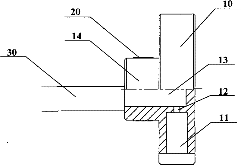
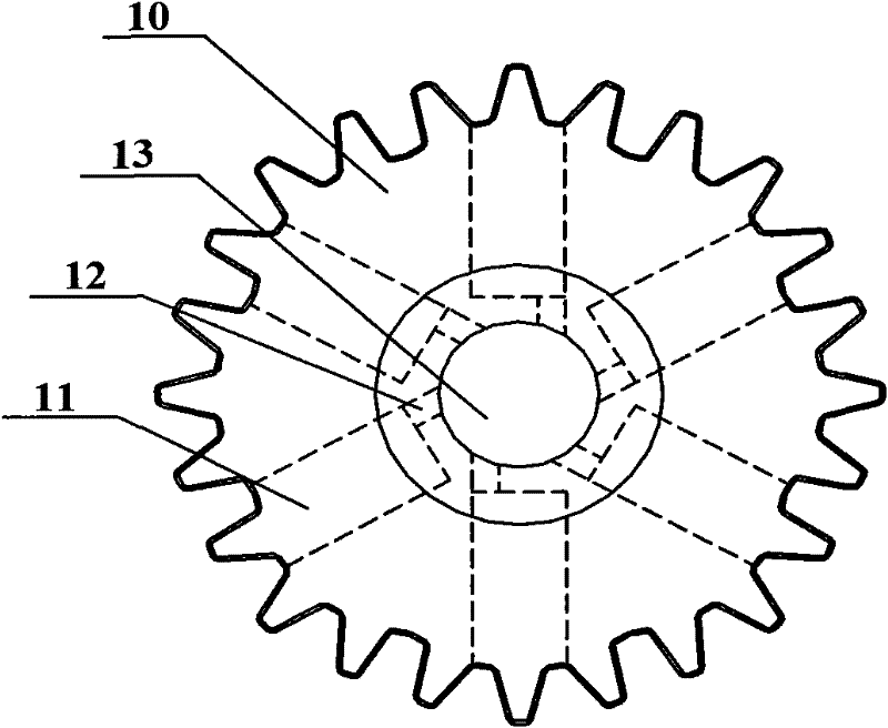
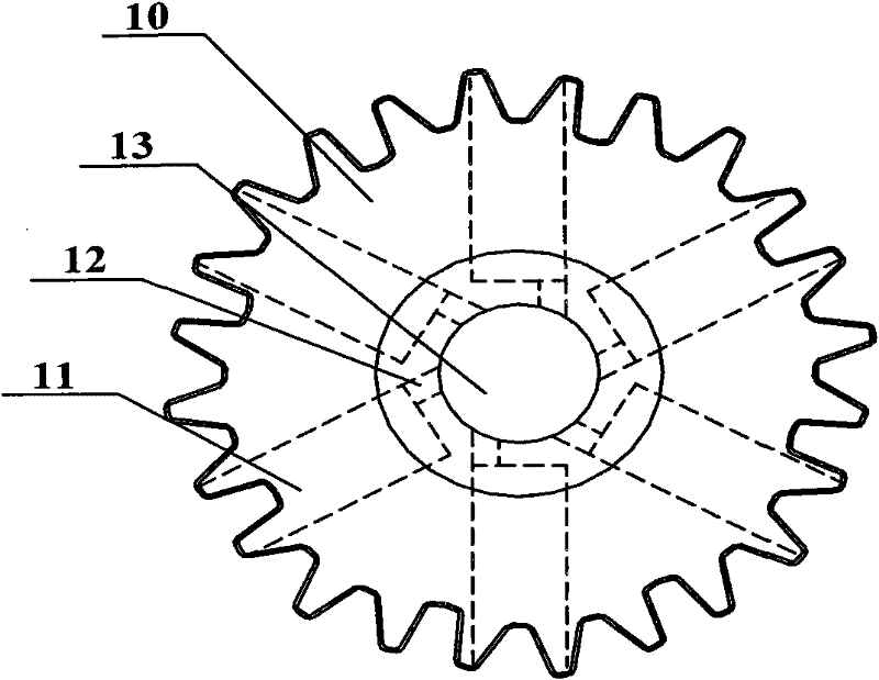
[0014] Such as Figure 1 to Figure 3 Shown, the engine oil-gas separation device embodiment of the present invention comprises:

[0015] The gear 10 located inside the engine, the gear shaft 14 on the gear 10 is closely matched with the supporting bearing 20, the supporting bearing 20 is installed in the engine gear chamber, and the gear 10 meshes with other gears of the engine;

[0016] The radial direction of the gear 10 is drilled with a first through hole 11 from outside to inside, and its gear shaft 14 is axially provided with a third through hole 13, and the first through hole 11 communicates with the third through hole 13; the third through hole 13 passes through Passage 30 communicates with the outside of the engine.

[0017] When the engine is running, the gear 10 of the engine oil-gas separation device of the present embodiment is driven by other gears to...


PUM


Abstract

The invention discloses an oil-gas separation device for an engine. The oil-gas device comprises a gear arranged in the engine, wherein a gear shaft on the gear is closely matched with a supporting bush; the supporting bush is installed in an engine gear chamber; the gear is meshed with other gears of the engine; the gear is provided with a first through hole in radial direction; the gear shaft is axially provided with a third through hole; the third through hole is communicated with the third through hole; and the third through hole is communicated with the external part of the engine via a path. In the oil-gas separation device for an engine, the linear speed of rotation of leak gas of a piston in the first through hole is higher because the gear rotates at a high speed when the gear operates, thereby achieving high oil-gas separation effect and high separation efficiency, The oil-gas separation device for an engine has the advantages of simple structure and lower cost.

Description

technical field [0001] The invention relates to a power machine, in particular to an engine oil-gas separation device. Background technique [0002] During the operation of the engine, a small part of the exhaust gas produced by the combustion of fuel in the combustion chamber will leak into the oil pan through the sealing gap of the piston ring. This part of the exhaust gas is called piston blow-by. Due to the high temperature inside the engine, the splash of engine oil, etc., the engine oil inside the engine will inevitably produce oil vapor, and the piston leakage of the engine will take away the atomized oil vapor during the process of exhausting the engine, resulting in engine oil leakage. increase in consumption. In order to reduce the oil consumption of the engine, a device must be provided to reduce the oil vapor contained in the blow-by air of the engine piston. [0003] Modern engines have a special system to complete the function of filtering out the oil vapor c...

Claims


Application Information

Patent Timeline
IPC IPC(8): F01M13/04
Inventor 杨剑李欢陶泽民
Owner GUANGXI YUCHAI MASCH CO LTD
Why Eureka
Try Eureka