
Wire bending fatigue test device

A bending fatigue and testing device technology, applied in the direction of applying repetitive force/pulse force to test the strength of materials, etc., can solve the problems of reducing the bending fatigue life of the cord, the large diameter of the bending pulley, and the low running speed of the whole machine, so as to improve the test Efficiency, reduced size, fast rotation effect

Active Publication Date: 2010-06-30
JIANGSU XINGDA STEEL TYPE CORD
View PDF0 Cites 7 Cited by
  • Summary
  • Abstract
  • Description
  • Claims
  • Application Information

AI Technical Summary

Problems solved by technology

The diameter of the bending pulley of this device is large, the running speed of the whole machine is low, the test efficiency is low, and the wire running is complicated, which reduces the bending fatigue life of the cord. After the bending fatigue test of the steel cord

Method used


Image

  • Wire bending fatigue test device
  • Wire bending fatigue test device
  • Wire bending fatigue test device

Examples


Embodiment Construction

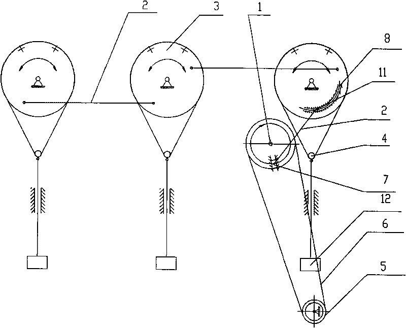
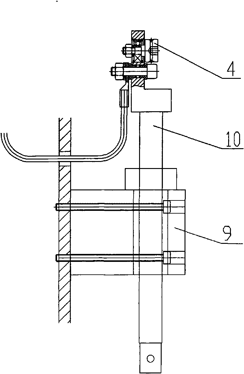
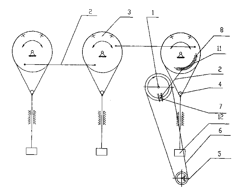
[0009] according to figure 1 and figure 2 As shown, a wire bending fatigue testing device of the present invention is mainly composed of a frame, a motor, an input shaft 1, a traction connecting rod 2, a balance wheel 3 and a roller 4, and the transmission device includes a reducer, a pulley 5 And transmission belt 6, motor drives speed reducer to carry out transmission, and speed reducer drives input shaft 1 to rotate by pulley 5, transmission belt 6. The end surface of the input shaft 1 is provided with a guide slider 7, and the guide slider 7 is provided with a long installation groove, and the bolt passes through the installation long groove to fix the guide slider 7 on the end surface of the input shaft 1. The driving end pin shaft of the traction link 2 is connected with the guide slider 7, the driven end pin shaft 11 of the traction link 2 is connected with the balance wheel 3, and the driven end pin shaft 11 is located in the arc groove 8 of the frame and can be move...


PUM


Abstract

The invention discloses a wire bending fatigue test device which comprises a frame and a motor as well as an input shaft (1), a tractive connecting link (2), a balance wheel (3) and a runner wheel (4). The motor drives the input shaft (1) to rotate through a transmission device; a guide and slide block (7) is arranged on the end surface of the input shaft (1); a pin shaft at the driving end of the tractive connecting link (2) is connected with the guide and slide block (7); a pin shaft (11) at the driven end of the tractive connecting link (2) is connected with the balance wheel (3) and positioned in an arc-shaped groove (8) of a frame to slide along the arc-shaped groove (8); wire grooves are formed on the peripheral surfaces of the balance wheel (3) and the runner wheel (4); after a to-be-detected wire passes through the wire grooves on the peripheral surfaces of the balance wheel (3) and the runner wheel (4), two ends of the to-be-detected wire are fixed on the balance wheel (3); the runner wheel (4) is hung under the balance wheel (3) by the to-be-detected wire; and a counter weight load (12) is hung on the runner wheel (4).

Description

technical field [0001] The invention relates to a wire bending fatigue testing device, in particular to a steel cord bending fatigue testing device. Background technique [0002] With the rapid development of the automobile industry, users put forward higher quality requirements for tires, and tire factories have higher and higher quality requirements for steel cords, and steel cord manufacturers continue to test the quality of cords. Increased, including torsional fatigue and bending fatigue tests of steel cords. Existing steel wire rope bending fatigue testing machine, it is mainly made up of driving wheel, bending pulley and load movable pulley etc., steel wire rope winds through driving wheel, bending pulley and load movable pulley and both ends are fixed on the driving wheel, drive driving wheel to do reciprocating motion with transmission shaft , to drive the bending pulley to make the sample perform plane unidirectional repeated bending within the effective length. ...

Claims


Application Information

Patent Timeline
Patent Type & Authority Applications(China)
IPC IPC(8): G01N3/34
Inventor 刘锦兰董玉华翟培云朱文芳
Owner JIANGSU XINGDA STEEL TYPE CORD
Learn More