Heat dissipation power distribution cabinet for communication

A power distribution cabinet and thermistor technology, which is applied in the substation/distribution device casing, electrical components, substation/switch layout details, etc. and other problems, to prevent rainwater from entering the power distribution cabinet, improve the heat dissipation effect, and achieve a good heat dissipation effect.

Inactive Publication Date: 2019-12-13
朱蛟龙
View PDF6 Cites 7 Cited by
  • Summary
  • Abstract
  • Description
  • Claims
  • Application Information

AI Technical Summary

Problems solved by technology

[0002] With the continuous development of communication technology, the number of outdoor power distribution cabinets is also increasing. The equipment in the power distribution cabinet will generate a lot of heat during operation, and in the high temperature state, the temperature in the power distribution cabinet will be It will be higher, it is easy to burn out the electrical components in the power distribution cabinet
[0003] The existing power distribution cabinets generally only have some vents or ventilation fences on the side walls of the power distribution cabinets. The heat dissipation effect of this heat dissipation measure cannot prevent high temperature exposure, and the heat dissipation effect is not good. It is easy to enter the power distribution cabinet, causing a short circuit of the electrical components in the power distribution cabinet, and even damaging the entire communication line, causing great economic losses and even threatening people's safety. Therefore, it is necessary to design a heat dissipation power distribution cabinet for communication

Method used


Image

  • Heat dissipation power distribution cabinet for communication
  • Heat dissipation power distribution cabinet for communication
  • Heat dissipation power distribution cabinet for communication

Examples


Embodiment Construction

[0019] The following will clearly and completely describe the technical solutions in the embodiments of the present invention with reference to the accompanying drawings in the embodiments of the present invention. Obviously, the described embodiments are only some, not all, embodiments of the present invention.

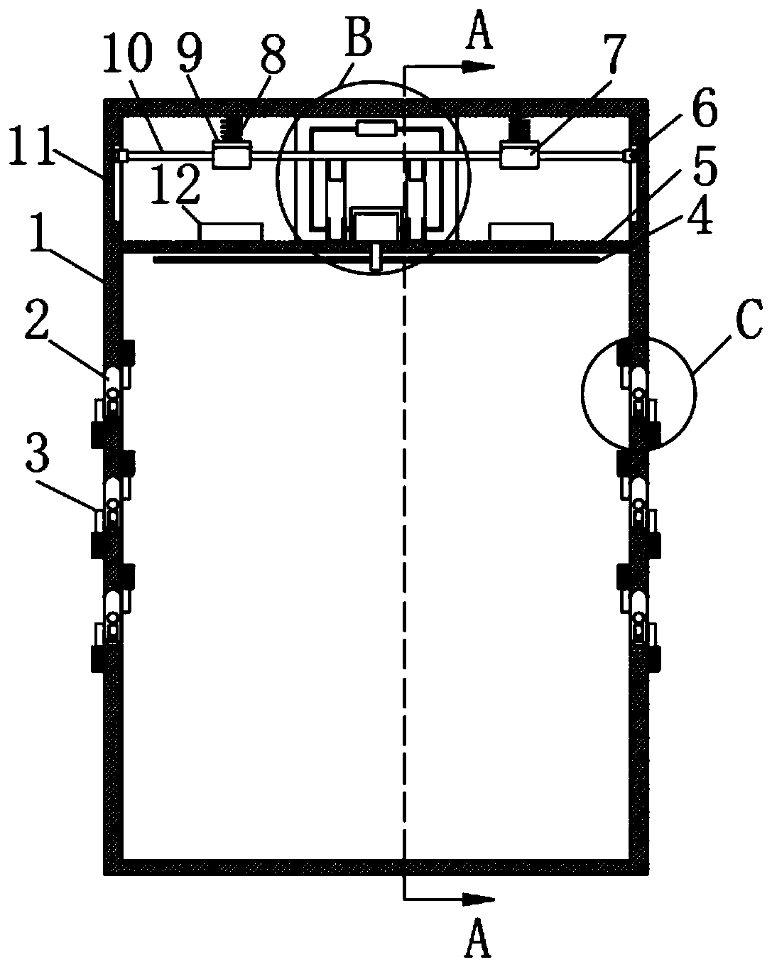
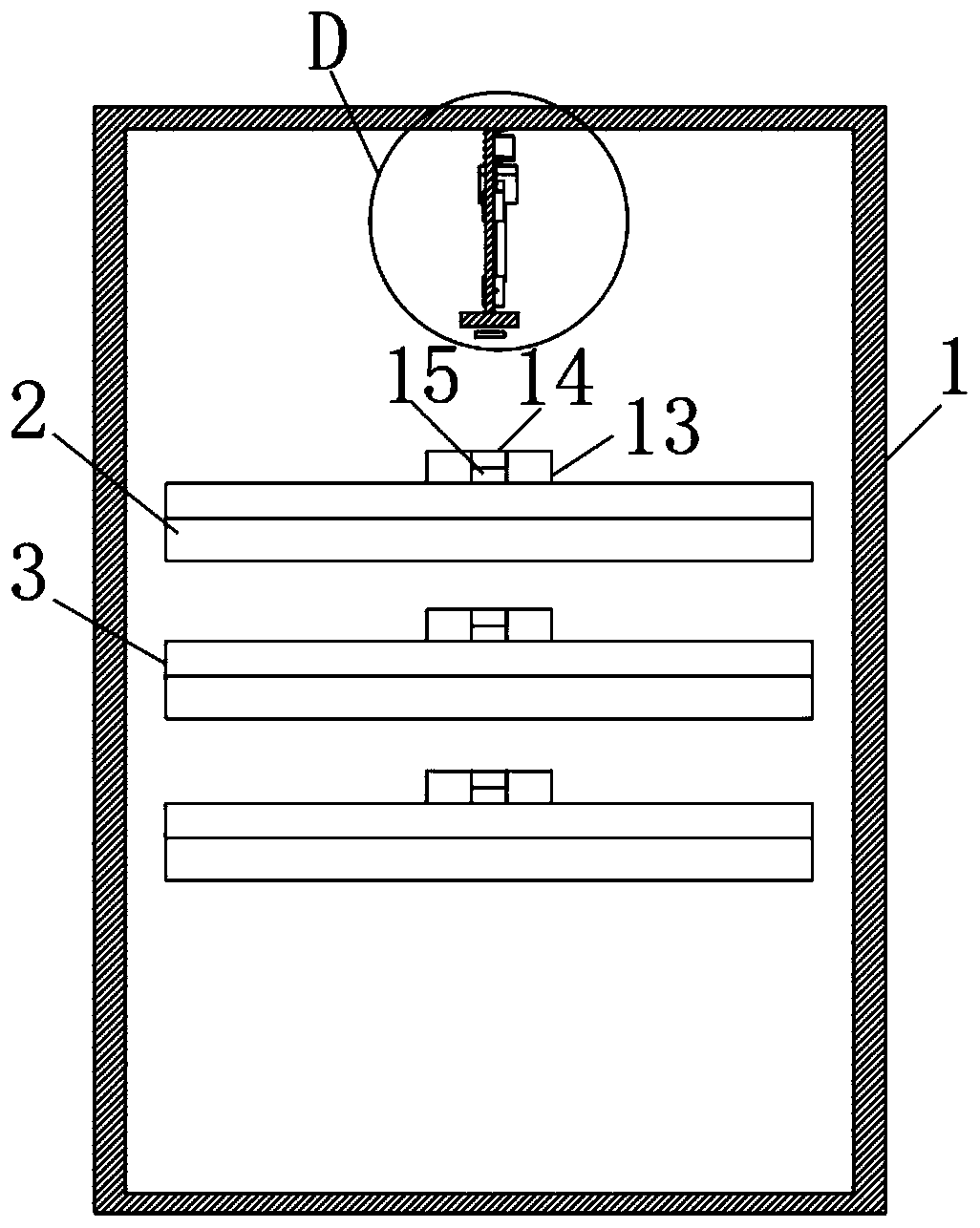
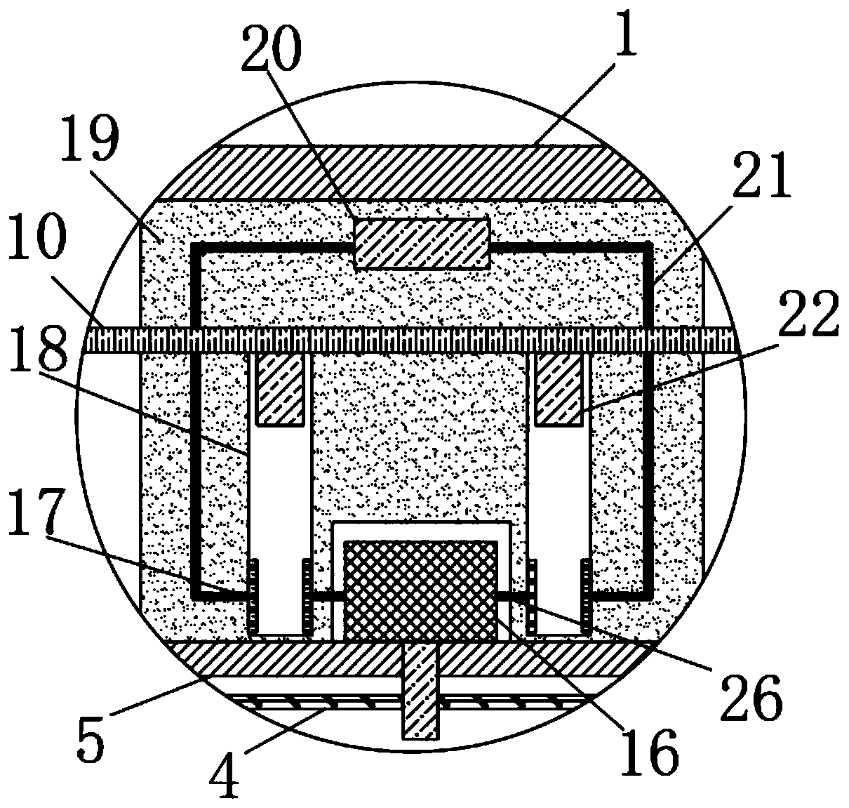
[0020] refer to Figure 1-5 , a heat dissipation power distribution cabinet for communication, comprising a cabinet body 1, a mounting plate 5 is fixedly connected to the inner wall near the upper end of the cabinet body 1, and a heat dissipation mechanism is provided at the upper end of the mounting plate 5, and the heat dissipation mechanism includes a heat dissipation mechanism fixedly connected to the upper wall of the mounting plate 5 The fixed plate 19, and the upper wall of the fixed plate 19 is fixedly connected with the upper inner wall of the cabinet body 1, the side wall near the lower end of the fixed plate 19 is provided with a mounting groove, the upper ...


PUM


Abstract

The invention discloses a heat dissipation power distribution cabinet for communication. The cabinet comprises a cabinet body. The inner wall, close to the upper end, of the cabinet body is fixedly connected with a mounting plate. A heat dissipation mechanism is arranged at the upper end of the mounting plate. The heat dissipation mechanism comprises a fixed plate fixedly connected to the upper wall of the mounting plate, and the upper wall of the fixed plate is fixedly connected with the upper inner wall of the cabinet body. A mounting groove is formed in the side wall, close to the lower end, of the fixed plate in a penetrating mode. A motor is arranged on the upper wall of the mounting plate and located in the mounting groove. An output shaft of the motor is fixedly connected with a rotating shaft, and a plurality of fan blades are fixedly connected to the side wall of the rotating shaft. A temperature controller is arranged on the side wall, close to the upper end, of the fixed plate. When the temperature is high, electrical components in the power distribution cabinet are cooled. The higher the temperature is, the faster the fan blades rotate. The heat dissipation effect of the device can be further improved through cooperation of rotation of a ventilation plate and the fan blades. Rainwater can be prevented from entering the power distribution cabinet in rainy days, and the electrical components are protected.

Description

technical field [0001] The invention relates to the technical field of power distribution equipment for communication, in particular to a heat dissipation power distribution cabinet for communication. Background technique [0002] With the continuous development of communication technology, the number of outdoor power distribution cabinets is also increasing. The equipment in the power distribution cabinet will generate a lot of heat during operation, and in the high temperature state, the temperature inside the power distribution cabinet will be It will be higher, and it is easy to burn out the electrical components in the power distribution cabinet. [0003] The existing power distribution cabinets generally only have some vents or ventilation fences on the side walls of the power distribution cabinets. The heat dissipation effect of this heat dissipation measure cannot prevent high temperature exposure, and the heat dissipation effect is not good. It is easy to enter the...

Claims


Application Information

Patent Timeline
Patent Type & Authority Applications(China)
IPC IPC(8): H02B1/30H02B1/56H02B1/28
CPCH02B1/28H02B1/30H02B1/565
Inventor 朱蛟龙
Owner 朱蛟龙
Why Eureka
Try Eureka