Vacuum pump

a vacuum pump and pump body technology, applied in the field of vacuum pumps, can solve the problems of high cost and achieve the effect of reducing the cost of the pump, facilitating the rotation of the shaft, and contributing to the cost-effectiveness and compactness of the inventive vacuum pump

Inactive Publication Date: 2010-01-28
PFEIFFER VACUUM GMBH
View PDF7 Cites 7 Cited by
  • Summary
  • Abstract
  • Description
  • Claims
  • Application Information

AI Technical Summary

Benefits of technology

[0015]According to the present invention, the shaft material substantially consists of silicon carbide. This material combines the compatibility with the gas bearings with stability of the vacuum pump in different applications.
[0016]According to the present invention, the rotor and the stator of the drive motor of the vacuum pump are so formed that they provide for an axial centering and, simultaneously, a rapid rotation of the shaft. This permits to eliminate the need for axial bearings, which further contributes to cost-effectiveness and compactness of the inventive vacuum pump.

Problems solved by technology

However, the proposed construction, because of its rather high costs, is only attractive for class of pumps having a suction capacity above 20 m3 / hr.

Method used


Image

  • Vacuum pump
  • Vacuum pump
  • Vacuum pump

Examples


Embodiment Construction

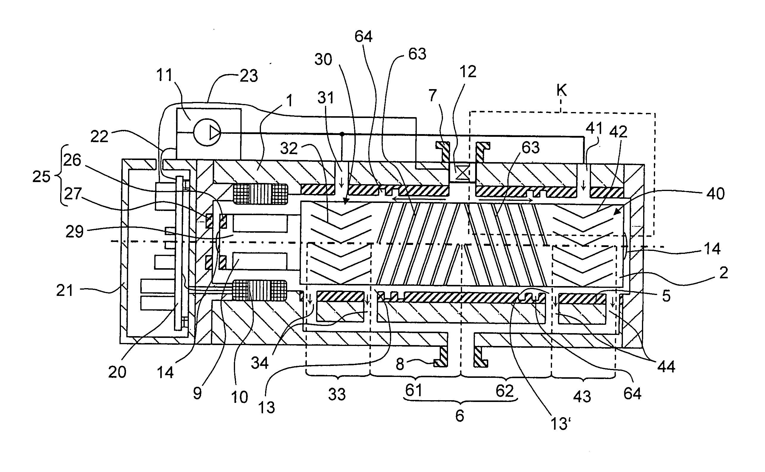
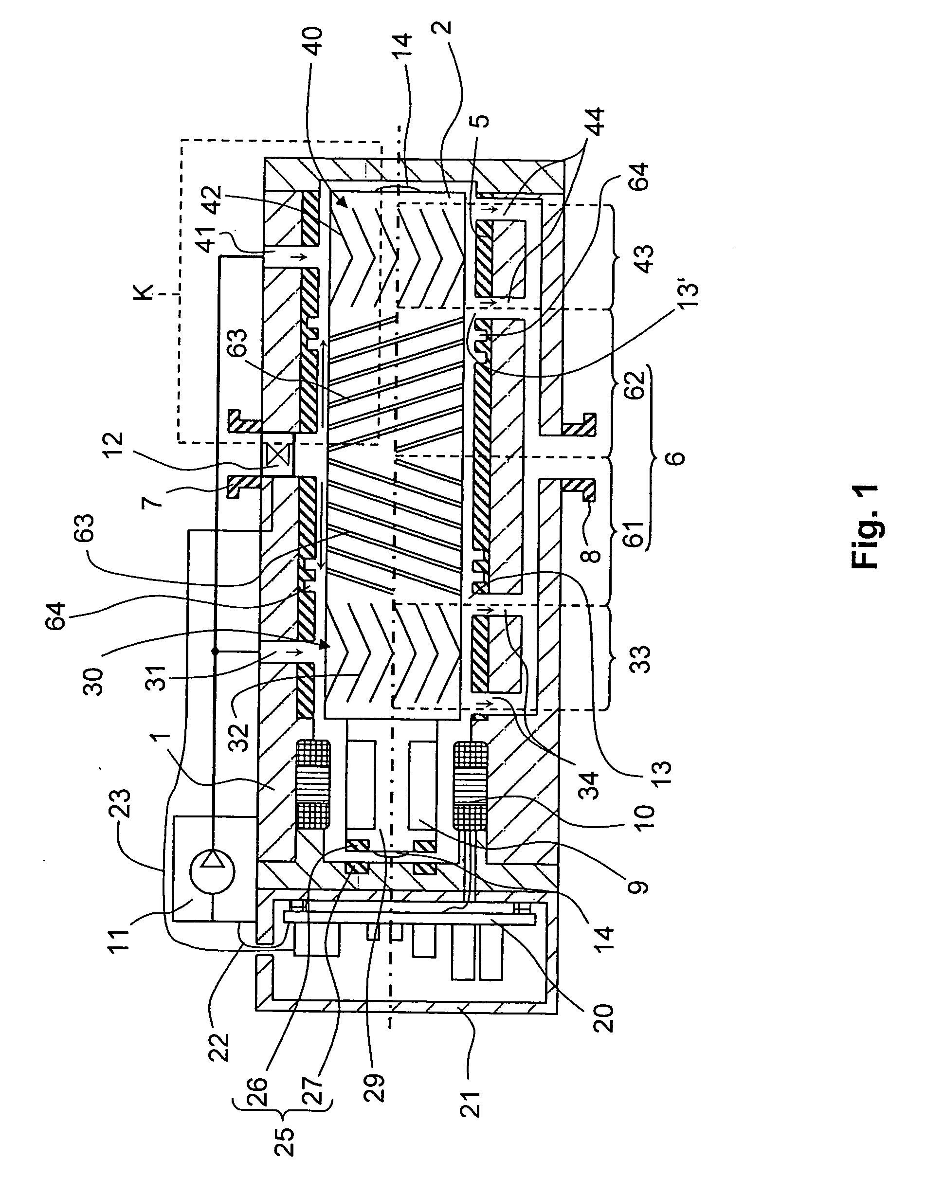
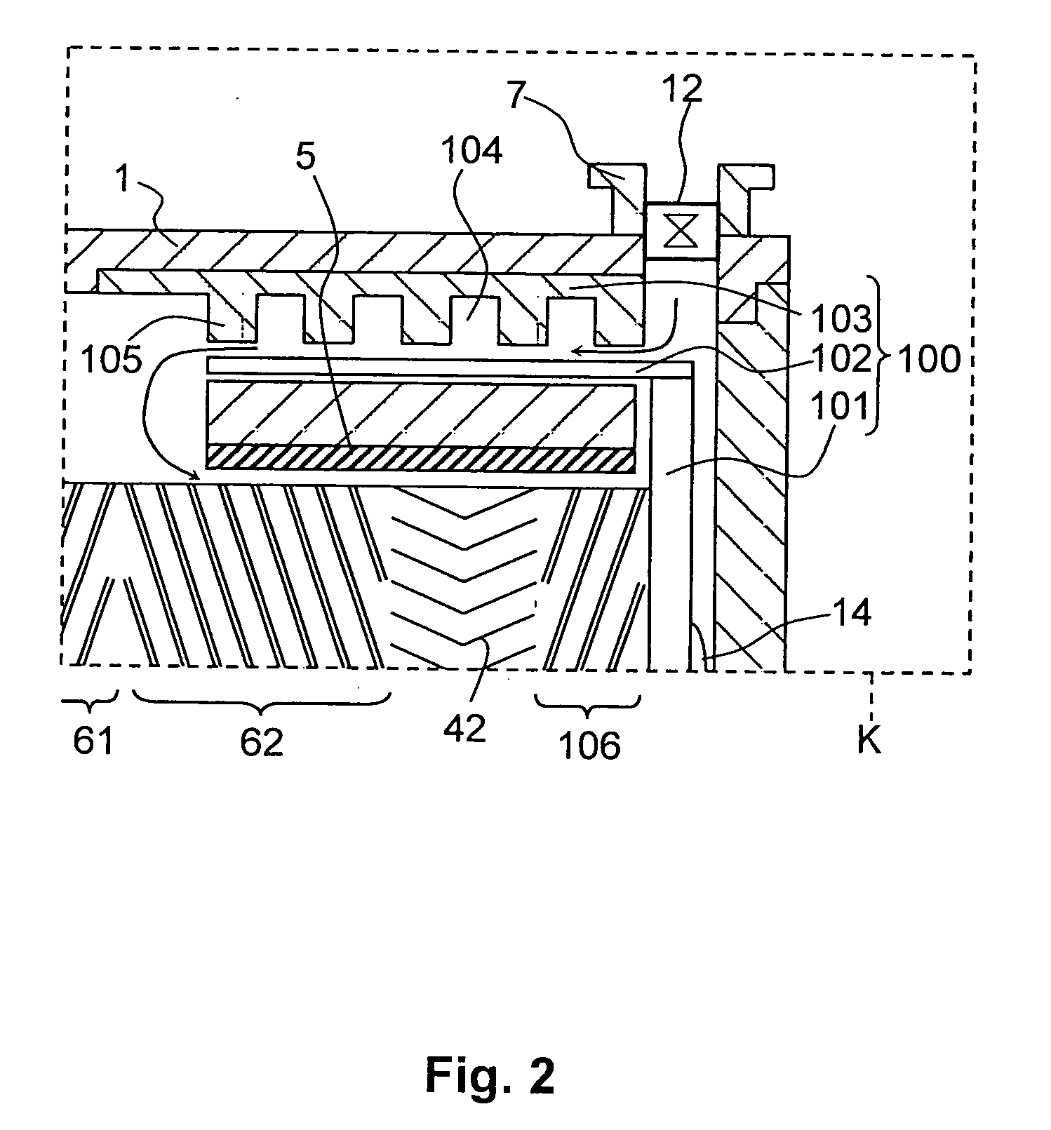
[0021]A vacuum pump according to the present invention, which is shown in FIG. 1, has a housing 1 having a gas inlet 7 and a gas outlet 8. Inside the housing 1, there is arranged a cylinder 5 in which a shaft 2 is rotatably supported. At its opposite ends, the shaft is supported by two gas bearings 30 and 40, respectively.

[0022]The first gas bearing 30 includes a gas inlet 31, a shaft-side bearing structure 32 and a bearing gas outlet 34. The bearing structure 32 forms a bearing section 33 extending in the shaft axial direction.

[0023]The second gas bearing 40 includes a gas inlet 41, a shaft-side bearing structure 42 and a bearing gas outlet 44. The bearing structure 42 forms a bearing section 43 extending in the shaft axial direction.

[0024]The bearing structures 32 and 42 include recesses formed in the surface of the shaft 2.

[0025]In the embodiment shown in FIG. 1, each of the gas bearing outlets 34 and 44 is provided with two openings located, respectively, at opposite ends of the...


PUM


Abstract

A vacuum pump includes shaft, two spaced from each other, dynamic gas bearings for supporting the shaft for rotation, and a pumping system arranged on the shaft between the two gas bearings and having two pumping sections which are so formed that compressed gas from each section is delivered in a direction of a gas bearing adjacent to this pumping section.

Description

BACKGROUND OF THE INVENTION[0001]1. Field of the Invention[0002]The present invention relates to a vacuum pump having a shaft supported for rotation by two radial bearings, and a pumping system arranged on the shaft.[0003]2. Description of the Prior Art[0004]In many technical fields, the production of a high vacuum with pressures lower than 10−4 mbar is of great importance. There is an increasing need in compact vacuum pumps capable of producing such pressures. In the state of the art, however, often, pumping stations are used. In the pumping stations, several separate pumps, which are adapted to particular pressure regions, are combined. Recently, vacuum pumps dischargeable into atmosphere have been developed. In these pumps, several pumping principles are combined. E.g., the German Publication DE 199 30 952 A1 proposes to combine Holweck pumping stages with peripheral stages. However, the proposed construction, because of its rather high costs, is only attractive for class of pump...

Claims


Application Information

Patent Timeline
Patent Type & Authority Applications(United States)
IPC IPC(8): F04D29/046
CPCF04D29/057F04D19/044
Inventor CONRAD, ARMIN
Owner PFEIFFER VACUUM GMBH
Why Eureka
Try Eureka