Scanning device and laser radar

A technology of scanning device and rotating bracket, which is applied in the field of scanning device and laser radar, can solve the problems that the laser radar solution cannot meet the performance requirements, and achieve the effects of low power consumption, wide range of scanning angles, and good environmental adaptability

Pending Publication Date: 2019-05-31
O NET COMM (SHENZHEN) LTD
View PDF6 Cites 8 Cited by
  • Summary
  • Abstract
  • Description
  • Claims
  • Application Information

AI Technical Summary

Problems solved by technology

[0006] The technical problem to be solved by the present invention is to provide a scanning device and a laser radar to solve the problem that the existing laser radar solution cannot meet the performance requirements of the industry in view of the above-mentioned defects of the prior art

Method used


Image

  • Scanning device and laser radar
  • Scanning device and laser radar
  • Scanning device and laser radar

Examples


Embodiment Construction

[0032] Now in conjunction with the accompanying drawings, the preferred embodiments of the present invention will be described in detail.

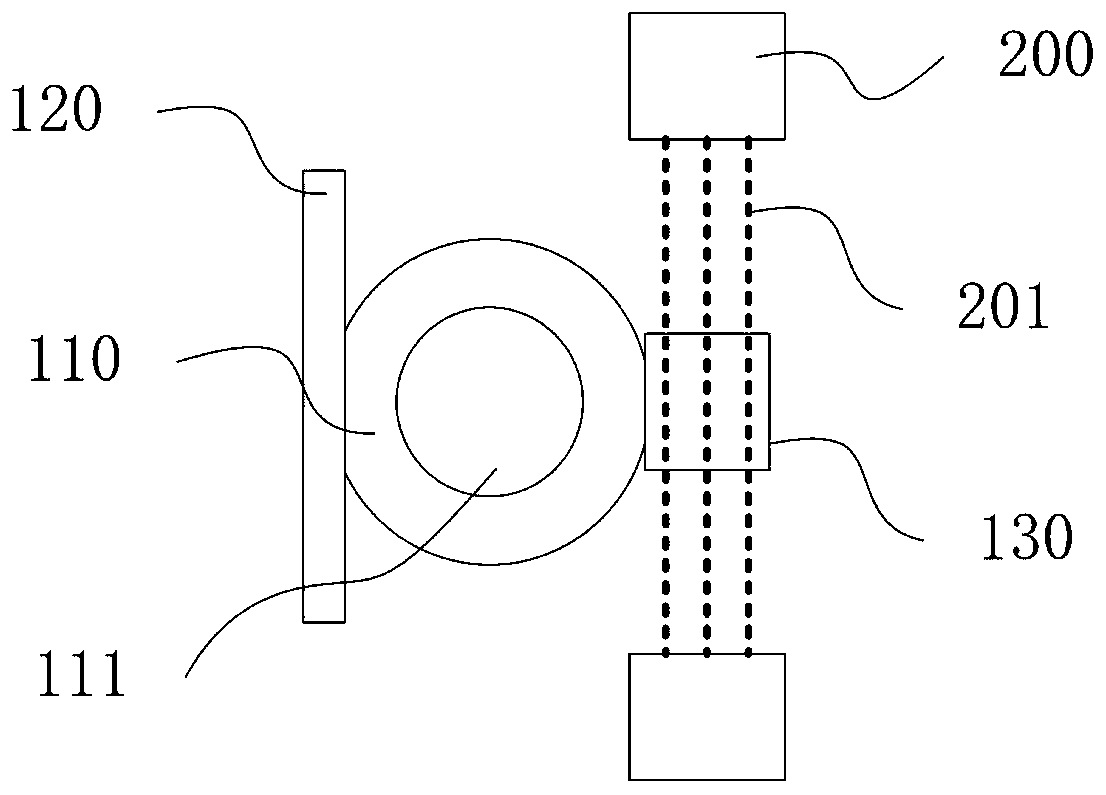
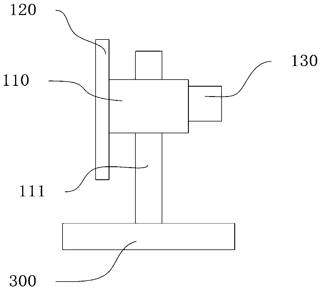
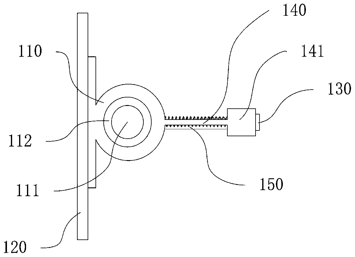
[0033] Such as figure 1 with figure 2 As shown, the present invention provides a preferred embodiment of a scanning device.

[0034] A scanning device, comprising a rotating bracket 110, a mirror 120, a magnetic piece 130 and a magnetic field generating mechanism 200; wherein, the rotating bracket 110 is rotatable, the mirror 120 is fixed on the rotating bracket 110, and the magnetic piece 130 is fixed on a rotating On the bracket 110 , the magnetic field generating mechanism 200 generates a magnetic field 201 with a variable direction. The magnetic element 130 is set in the magnetic field 201 and moves back and forth under the action of the magnetic field 201 to drive the rotating bracket 110 to rotate back and forth.

[0035] Specifically, the reflector 120 is fixed on the rotating bracket 110 and rotates as the rotating bracket 110 r...


PUM


Abstract

The invention relates to the field of laser radar, and particularly relates to a scanning device. The scanning device comprises: a rotation support capable of rotation motion around a rotation shaft;a reflector fixedly arranged on the rotation support; a magnetic member fixedly arranged on the rotation support; and a magnetic field generating mechanism generating a magnetic field having a variable direction, wherein the magnetic member is arranged in the magnetic field and performs reciprocation under the action of the magnetic field to drive the reciprocation rotation of the rotation support. The present invention further relates to a laser radar. Compared to a rotation scanning system driven by a motor, the scanning device is small in size and fast in rotation speed, high in efficiency,compared to a traditional galvanometer scanning system, the scanning device is lower in cost, smaller in size, lower in power consumption and better in environmental adaptability, and compared to a MEMS system, the scanning device is larger in scanning area and wider in scanning angle range and is closer to the practicality.

Description

technical field [0001] The invention relates to the field of laser radar, in particular to a scanning device and laser radar. Background technique [0002] Lidar is a radar system that emits laser beams to detect characteristic quantities such as the position and speed of targets. Its working principle is to send a detection signal (laser beam) to the target, and then compare the received signal (target echo) reflected from the target with the transmitted signal, and after proper processing, the relevant information of the target can be obtained, such as Parameters such as target distance, azimuth, height, speed, attitude, and even shape. [0003] Especially in the field of autonomous driving, technologies such as autonomous driving are developing rapidly. One of the important supporting sensors, lidar, has emerged various types of solutions in order to meet various specific needs. [0004] At present, the solutions for lidar scanning mainly include motor-driven rotary sca...

Claims


Application Information

Patent Timeline
Patent Type & Authority Applications(China)
IPC IPC(8): G01S7/481
CPCG01S7/481G01S17/02
Inventor 任建峰虞爱华
Owner O NET COMM (SHENZHEN) LTD
Why Eureka
Try Eureka