
Test box for sandy soil geotechnical model

A technology of geotechnical model and test chamber, which is applied in the direction of soil material testing, preparation of test samples, material inspection products, etc., can solve the problem of being unable to further explore two-dimensional seepage, unable to complete sample preparation and test work, and difficult to meet the requirements of sample preparation. Requirements and other issues to achieve the effect of two-dimensional seepage, reasonable design, and wave elimination

Pending Publication Date: 2020-01-17
INST OF ENG MECHANICS CHINA EARTHQUAKE ADMINISTRATION
View PDF13 Cites 3 Cited by
  • Summary
  • Abstract
  • Description
  • Claims
  • Application Information

AI Technical Summary

Problems solved by technology

[0002] As an important tool used in the sandy soil geotechnical model test, the test box has a simple structure and a single function, and can only perform auxiliary sample preparation by a single method, and cannot complete complex sample preparation and test work, which affects the further in-depth test exploration. The sample preparation method has been greatly developed. Therefore, the existing sample box with a simple box body and a bottom drain structure has been difficult to meet the increasingly advanced and diverse sample preparation requirements. The simple box structure has led to In the earthquake simulation shaking table test, the pore water can only do one-dimensional seepage upwards, and the problem of two-dimensional seepage cannot be further explored. It will also cause waves to reverberate on the surface of the sample during the vibration process, which will cause errors in the experimental results.

Method used


Image

  • Test box for sandy soil geotechnical model
  • Test box for sandy soil geotechnical model
  • Test box for sandy soil geotechnical model

Examples


Embodiment Construction

[0020] In order to make the object, technical solution and advantages of the present invention clearer, the present invention will be further described in detail below in combination with specific embodiments and with reference to the accompanying drawings. It should be understood that these descriptions are exemplary only, and are not intended to limit the scope of the present invention. Also, in the following description, descriptions of well-known structures and techniques are omitted to avoid unnecessarily obscuring the concept of the present invention.

[0021] It should be noted that the terms "first" and "second" in the specification, claims and drawings of the present application are used to distinguish similar objects, but not necessarily used to describe a specific order or sequence. It is to be understood that the terms so used are interchangeable under appropriate circumstances such that the embodiments of the application described herein are, for example, capable ...


PUM

PropertyMeasurementUnit
Diameteraaaaaaaaaa

Abstract

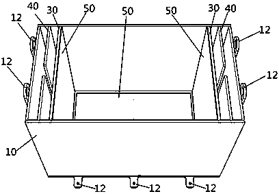
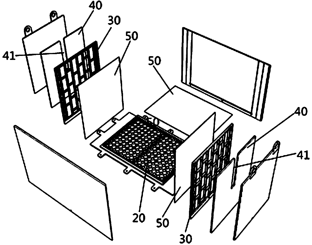
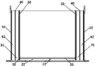
The invention discloses a test box for a sandy soil geotechnical model. The test box comprises a box body, a supporting part, a liquid level control plate and three water permeable plates, wherein thewater permeable plates are made of sintered metal and are detachably connected with a corresponding bottom supporting plate and two corresponding side supporting plates respectively; a first cavity layer is arranged between the bottom supporting plate and the inner wall of the bottom of the box body; a second cavity layer is arranged between the side supporting plates and the liquid level controlplate; a third cavity layer is arranged between the liquid level control plate and the side wall of the box body; a first water through hole is formed in the first cavity layer; a second water through hole is formed in the third cavity layer; the first cavity layer and the water permeable plates are arranged at the bottom of the box body to form a buffering through-flow system, so that the impactdamage of fluid to the model is avoided and the introduction efficiency of the fluid is guaranteed; the second cavity layer, the water permeable plates, the liquid level control plate and the third cavity layer are arranged on the two sides of the box body to form a water permeable wave absorbing system, so that pore pressure accumulation is eliminated, and two-dimensional seepage and wave elimination are realized.

Description

technical field [0001] The invention relates to the technical field of geotechnical testing, in particular to a test box for a sandy soil geotechnical model. Background technique [0002] As an important tool used in the sandy soil geotechnical model test, the test box has a simple structure and a single function, and can only perform auxiliary sample preparation by a single method, and cannot complete complex sample preparation and test work, which affects the further in-depth test exploration. The sample preparation method has been greatly developed. Therefore, the existing sample box with a simple box body and a bottom drain structure has been difficult to meet the increasingly advanced and diverse sample preparation requirements. The simple box structure has led to In the earthquake simulation shaking table test, the pore water can only do one-dimensional seepage upwards, and the two-dimensional seepage cannot be further explored. It will also cause waves to reverberate ...

Claims


Application Information

Patent Timeline
IPC IPC(8): G01N33/24G01N19/00G01N1/28
CPCG01N33/24G01N19/00G01N1/28
Inventor 汪云龙王义德陈龙伟
Owner INST OF ENG MECHANICS CHINA EARTHQUAKE ADMINISTRATION
Learn More