A security terminal based on face recognition
A face recognition and security terminal technology, applied in the camera body, color TV parts, TV system parts and other directions, can solve the problem of the shooting angle cannot be adjusted, the applicability is not good, and achieve good protection effect Effect
- Summary
- Abstract
- Description
- Claims
- Application Information
AI Technical Summary
Problems solved by technology
Method used
Image
Examples
Embodiment 1
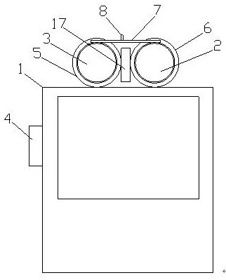
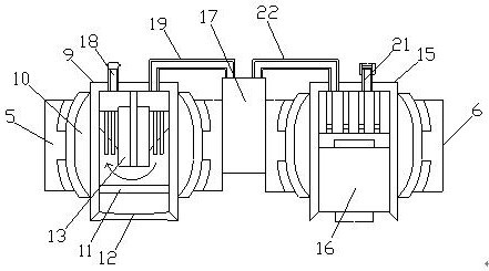
[0027] Such as Figure 1-3 As shown, a security terminal based on face recognition includes a controller 1, a camera 2 and a lighting device 3, the lighting device 3 and the camera 2 are electrically connected to the controller 1, and the controller 1 A light sensor 4 is provided, and the light sensor 4 is electrically connected to the controller 1, and the upper end of the controller 1 is provided with a first joint bearing 5 and a second joint bearing 6, and the first joint bearing 5 and the second joint bearing The bearings 6 are all fixedly connected to the controller 1, the lighting device 3 and the imaging device 2 are installed in the first joint bearing 5 and the second joint bearing 6 respectively, and the lighting device 3 and the imaging device 2 pass through the first joint bearing respectively 5 and the second joint bearing 6 are movably connected, and a connecting rod 7 is arranged above the lighting device 3 and the camera device 2, and the lighting device 3 and...
Embodiment 2
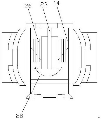
[0030] Such as Figure 1-4 As shown, a security terminal based on face recognition includes a controller 1, a camera 2 and a lighting device 3, the lighting device 3 and the camera 2 are electrically connected to the controller 1, and the controller 1 A light sensor 4 is provided, and the light sensor 4 is electrically connected to the controller 1, and the upper end of the controller 1 is provided with a first joint bearing 5 and a second joint bearing 6, and the first joint bearing 5 and the second joint bearing The bearings 6 are all fixedly connected to the controller 1, the lighting device 3 and the imaging device 2 are installed in the first joint bearing 5 and the second joint bearing 6 respectively, and the lighting device 3 and the imaging device 2 pass through the first joint bearing respectively 5 and the second joint bearing 6 are movably connected, and a connecting rod 7 is arranged above the lighting device 3 and the camera device 2, and the lighting device 3 and...
PUM
 Abstract
Description
Claims
Application Information
 - R&D
- Intellectual Property
- Life Sciences
- Materials
- Tech Scout
- Unparalleled Data Quality
- Higher Quality Content
- 60% Fewer Hallucinations
Browse by: Latest US Patents, China's latest patents, Technical Efficacy Thesaurus, Application Domain, Technology Topic, Popular Technical Reports.
© 2025 PatSnap. All rights reserved.Legal|Privacy policy|Modern Slavery Act Transparency Statement|Sitemap|About US| Contact US: help@patsnap.com


