Throwing-hanging type grounding device

A grounding device and grounding wire technology, applied in the direction of connection, conductive connection, electrical connection seat, etc., can solve the problems of increasing the workload of operators, increasing the complexity of the operation, and prolonging the working time, so as to reduce the number of hanging attempts and improve the Success rate, the effect of improving safety

Active Publication Date: 2020-01-17
ZAOZHUANG POWER SUPPLY COMPANY OF STATE GRID SHANDONG ELECTRIC POWER +1
View PDF8 Cites 3 Cited by
  • Summary
  • Abstract
  • Description
  • Claims
  • Application Information

AI Technical Summary

Problems solved by technology

[0003] The inventor found that in the actual maintenance work, due to the limitation of the structure of the traditional grounding wire and the way of hanging, when hanging, the operator needs to throw the insulating rope, and accurately connect the opening of the grounding wire chuck to the wire, and the wire can only be clamped after the wire hits the tongue. However, every time the operator hangs a grounding wire, they need to try many times to succeed; when facing a tension tower with a large corner, the wire is far away from the cross arm, and the installation is more difficult, and even forced to change the installation. Towers, this will greatly prolong the working time, increase the workload of operators, and bring great potential safety hazards; there are other grounding wire structures, although the opening of the hook is enlarged, or it is not equipped with insurance, which is easy to fall off, or it is installed after the insurance is installed. The complexity of its operation is greatly increased; the existing traditional grounding wire is difficult to meet the requirements of high work efficiency, less workload, and small safety hazards during the suspension process; it is difficult to ensure safe and reliable successful installation of the grounding wire

Method used


Image

  • Throwing-hanging type grounding device
  • Throwing-hanging type grounding device
  • Throwing-hanging type grounding device

Examples


Embodiment 1

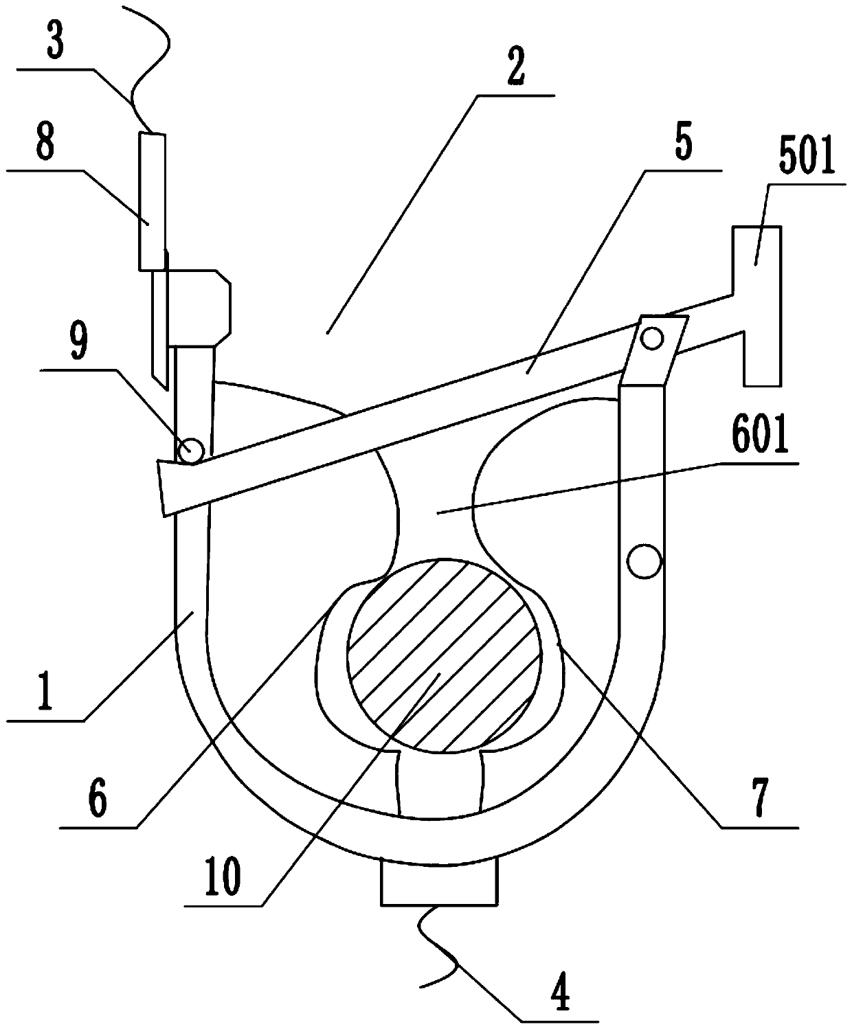
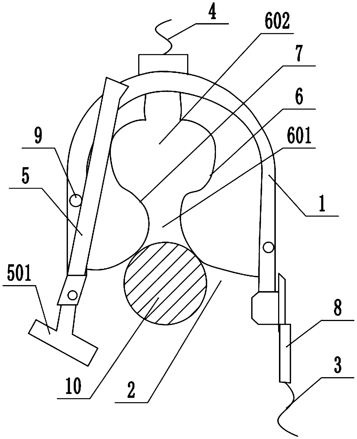
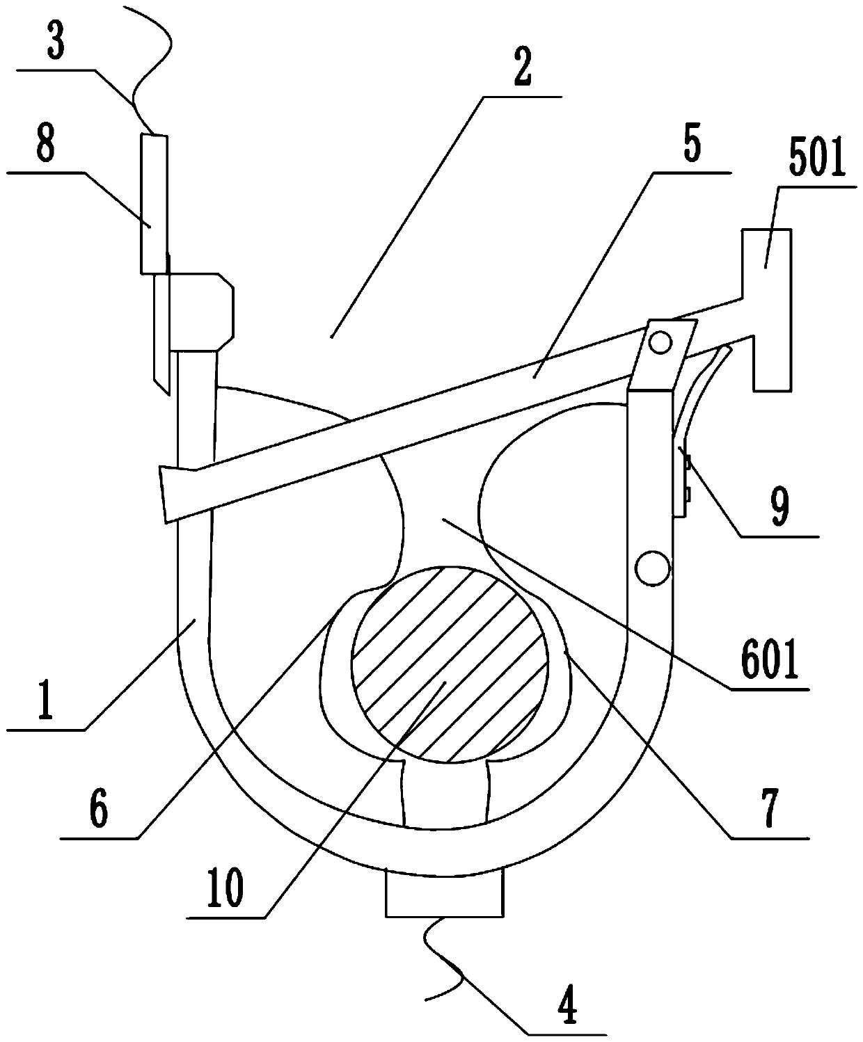
[0034] In a typical implementation of the present application, such as Figure 1-Figure 4 As shown, a throwing type grounding device is proposed.

[0035] Its main body is a U-shaped hook 1. The hook has an opening as the first opening 2. The wire 10 can pass through the first opening 2 and enter the inside of the hook. The first opening is equipped with a blocking rod 5, which is hinged on one side of the first opening, and the blocking rod rotates around its hinge point under the action of gravity, and has two extreme positions during its rotation, two Limiting blocks 9 are respectively arranged at the limit positions to contact the stop bar and block its further rotation, so that the stop bar can only rotate between the two stop blocks; when the stop bar rotates to contact the first stop block, the stop bar The rod seals the first opening, so that the wire is enclosed in the hook, preventing the wire from falling off from the hook; when the hook needs to be released, the s...


PUM


Abstract

The invention discloses a throwing-hanging type grounding device. The device comprises a hook, the hook is of a U-shaped structure with a first opening, and the interior of the first opening is used for accommodating a wire. The hook is connected with a first rope and a second rope which are used for adjusting the orientation of the first opening of the hook, and a stop lever is arranged at the first opening, is hinged to one side of the first opening and rotates around a hinge point under the action of gravity, and is used for closing the first opening to limit the wire in the first opening,or opening the first opening to form a channel through which the wire can pass. The hook with the opening is matched with the stop lever for intermittently closing the opening, the stop lever is controlled by the gravity to limit the falling of the wire or open the opening to detach the hook, and the whole process only needs to be controlled through the two ropes, so that the operation difficultyis reduced while the connection stability of the grounding wire and the wire is guaranteed, and the operation efficiency and the grounding efficiency are improved.

Description

technical field [0001] This application relates to the field of high voltage power transmission, in particular to a throwing type grounding device. Background technique [0002] In the process of maintenance or laying of transmission lines, each line is not live, but for safety, the electric power safety work regulations stipulate: After the line experience is clear that there is no voltage, the grounding wire should be installed immediately and the three-phase short circuit should be installed. The branches that may come to transmit power to the working section of the power outage line must be tested and installed with grounding wires. The complete set of grounding wires should be composed of multiple strands of soft copper wires with transparent sheaths, and the cross-sectional area must not be less than 25mm. 2 , the installation process should use insulating rods or special insulating ropes, and the human body is not allowed to touch the ungrounded wires; Personnel thro...

Claims


Application Information

Patent Timeline
Patent Type & Authority Applications(China)
IPC IPC(8): H01R11/14H01R11/22H01R4/48H01R4/30H01R43/00H01R43/027
CPCH01R4/30H01R4/4809H01R11/14H01R11/22H01R43/007H01R43/027
Inventor 刘良春张申前赵峰印张效伟王建王福天王正运王思贤
Owner ZAOZHUANG POWER SUPPLY COMPANY OF STATE GRID SHANDONG ELECTRIC POWER
Why Eureka
Try Eureka