Spectrum allocation method and device for optical network, and computer storage medium

A spectrum allocation and optical network technology, applied in the field of optical network transmission, can solve the problem of time-consuming numbering, and achieve the effect of improving spectrum allocation efficiency and reducing time.

Active Publication Date: 2020-01-17
ZTE CORP
View PDF12 Cites 4 Cited by
  • Summary
  • Abstract
  • Description
  • Claims
  • Application Information

AI Technical Summary

Problems solved by technology

[0009] Embodiments of the present invention provide a spectrum allocation method, equipment, and computer storage medium for an optical network, which can solve the problem that wavelengths cannot be numbered and the matrix method consumes a lot of time when spectrum allocation is performed on an elastic optical network

Method used


Image

  • Spectrum allocation method and device for optical network, and computer storage medium
  • Spectrum allocation method and device for optical network, and computer storage medium
  • Spectrum allocation method and device for optical network, and computer storage medium

Examples


no. 1 example

[0030] The embodiments of the present invention can implement frequency spectrum allocation in an optical network. Here, the optical network can be an elastic optical network or other optical networks.

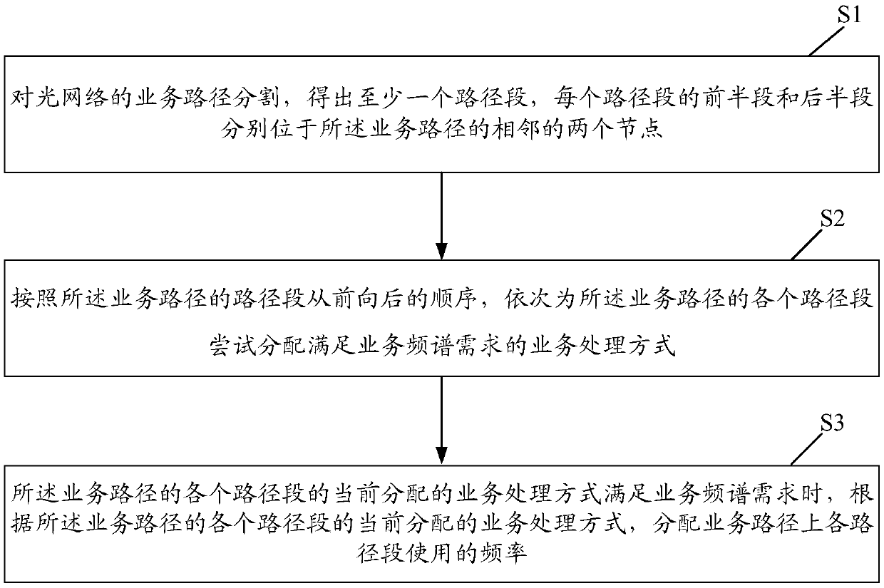
[0031] The first embodiment of the present invention describes a spectrum allocation method for an optical network, figure 2 It is the flow of the spectrum allocation method of the optical network according to the embodiment of the present invention Figure 1 ,like figure 2 As shown, the process can include:

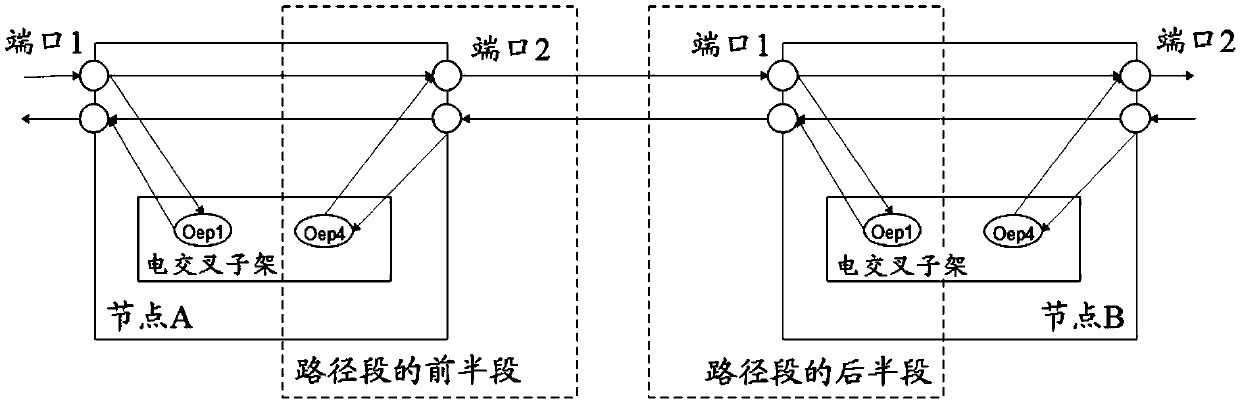
[0032] Step S1: Divide the service path of the optical network to obtain at least one path segment, and the first half and the second half of each path segment are respectively located at two adjacent nodes of the service path.

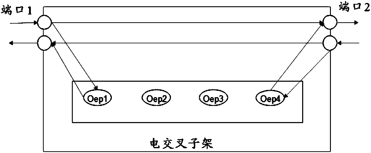
[0033] Here, the service path of the optical network includes at least one node, each node has two ports in total, each port is a routing half-hop port, each node may include at least one electrical cross subrack, and the electrical cross su...

no. 2 example

[0081] In order to better reflect the purpose of the present invention, further illustrations are made on the basis of the first embodiment of the present invention.

[0082] Figure 4 It is the flow of the spectrum allocation method of the optical network according to the embodiment of the present invention Figure II ,like Figure 4 As shown, the process can include:

[0083] Step 401: Set the initial value of the route segment number segNo to 1.

[0084] Step 402: Judging whether all path segments on the service path have been constructed, if yes, execute step 407, if not, execute step 403.

[0085] Step 403: call procedure A to construct the path segment with sequence number segNo, judge whether the path segment with sequence number segNo is constructed successfully, if yes, execute step 404, if not, execute step 405

[0086] Step 404: Add 1 to the value of segNo, return to step 402.

[0087] Step 405: judging whether segNo is equal to 1, if segNo is equal to 1, it is...

no. 3 example

[0121] In order to better reflect the purpose of the present invention, further illustrations are made on the basis of the foregoing embodiments of the present invention.

[0122] Figure 8 It is a schematic diagram of an application scenario of an embodiment of the present invention, such as Figure 8 As shown, this scenario represents a scenario where nodes are directly connected during the spectrum allocation process. In this scenario, the service path includes 3 nodes, and these 3 nodes are node A, node B, and node C respectively, and each node is configured with The electrical cross-connect subracks, wherein the electrical cross-connect subracks set up by node A and node C are service access electrical cross-connect subracks; the ports passed by the service paths are port 2 of node A, port 1 of node B, and Port 2 and port 1 of node C, Oep1 and Oep4 represent different OEPs.

[0123] In actual implementation, two path segments can be obtained by segmenting the service pa...


PUM


Abstract

Provided in embodiments of the present invention are a spectrum allocation method and device for an optical network, and a computer storage medium, the method comprising: segmenting a service path ofan optical network to obtain at least one path segment, the first half segment and the second half segment of each path segment being located at two adjacent nodes of the service path, respectively; then, according to the sequence of the path segments of the service path from front to back, trying to allocate a service processing mode meeting the service spectrum requirement for each path segmentof the service path in sequence; and when the currently allocated service processing mode of each path segment of the service path meets the service spectrum requirement, allocating the use frequencyof each path segment on the service path according to the currently allocated service processing mode of each path segment of the service path.

Description

technical field [0001] Embodiments of the present invention relate to, but are not limited to, optical network transmission technologies, and in particular, relate to a spectrum allocation method, device, and computer storage medium in an optical network. Background technique [0002] In an Automatically Switched Optical Network (ASON), for the establishment of a Label Switched Path (LSP) of a service, it is necessary to use a path calculation method (Constraint-based Shortest Path) based on existing network topology resources. First, CSPF) to calculate. After the path calculation is completed, spectrum (or wavelength) resources need to be allocated to the routing hops on the path; among them, the available spectrum range of Optical Transport Network (OTN) is 191.275-196.075THz, 4.8THz in total. [0003] figure 1 It is a schematic diagram of the internal structure of a node of an optical network according to an embodiment of the present invention, such as figure 1 As show...

Claims


Application Information

Patent Timeline
Patent Type & Authority Applications(China)
IPC IPC(8): H04Q11/00
CPCH04Q11/0062H04Q2011/0086H04Q2011/0073H04J14/0257H04J14/0267
Inventor 肖述超
Owner ZTE CORP
Why Eureka
Try Eureka