Chain clamp type transplanting machine power transmission system

A technology of power transmission system and power transmission device, which is applied in the field of chain clamp type transplanter power transmission system, can solve the problems of difficulty in mechanized automatic seedling placement, high requirements for seedling placement accuracy, difficulty in improving transplanting speed, etc. Easy to repeat seedling delivery and missing seedlings, high efficiency of seedling picking, and short time difference

Pending Publication Date: 2020-01-21
HUNAN AGRICULTURAL UNIV
View PDF0 Cites 1 Cited by
  • Summary
  • Abstract
  • Description
  • Claims
  • Application Information

AI Technical Summary

Problems solved by technology

[0002] Transplanting on a high-speed transplanting machine, due to the influence of the speed of transporting seedlings, it has been difficult to increase the transplanting speed
Different from the reciprocating planting method of the hanging cup type transplanting mechanism, the chain clip type transplanting mechanism adopts the method of continuously rotating the chain clip, which has the possibility of further improving the transplanting speed. The precision requirement is high, and the mechanized automatic seedling placement is difficult. However, on the chain clip transplanter that uses manual seedling placement, the transplanting speed is usually lower than 5000 plants / row / hour, which seriously affects the transplanting speed
Therefore, it is an important problem to be solved urgently for those skilled in the art to design a kind of automatic seedling delivery device with excellent performance, to promote the chain clamp type transplanter to further improve the transplanting speed, and to overcome the slow problem of manual seedling release.

Method used


Image

  • Chain clamp type transplanting machine power transmission system
  • Chain clamp type transplanting machine power transmission system
  • Chain clamp type transplanting machine power transmission system

Examples


Embodiment Construction

[0036] In order to make the technical means, creative features, goals and effects achieved by the present invention easy to understand, the present invention will be further described below in conjunction with specific illustrations.

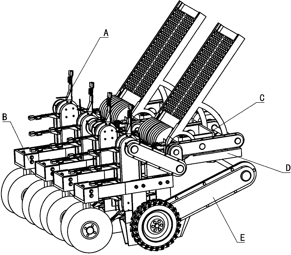
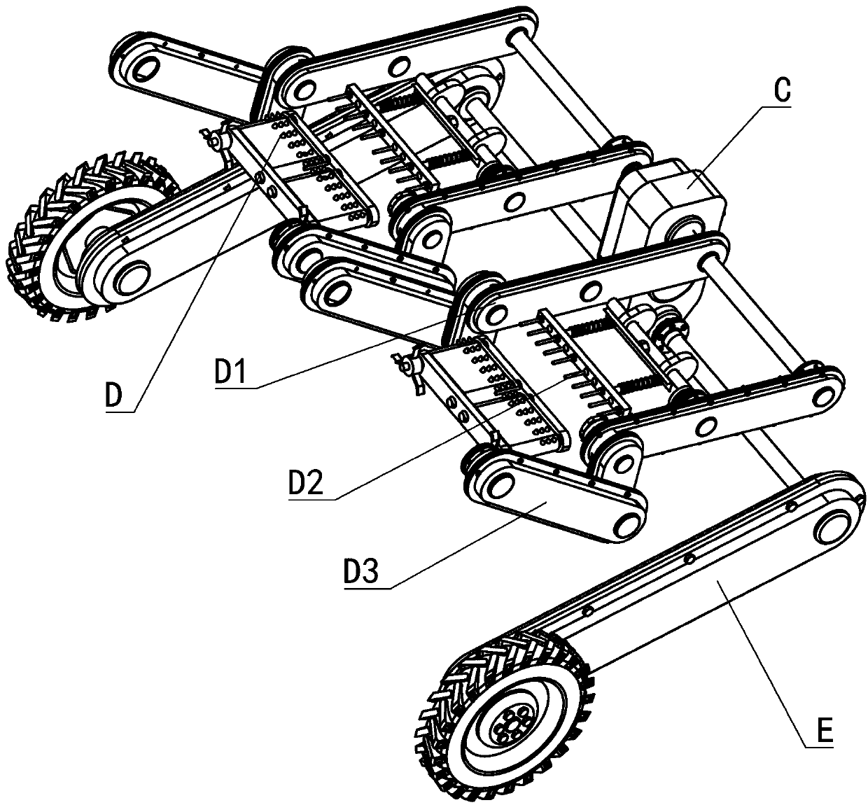
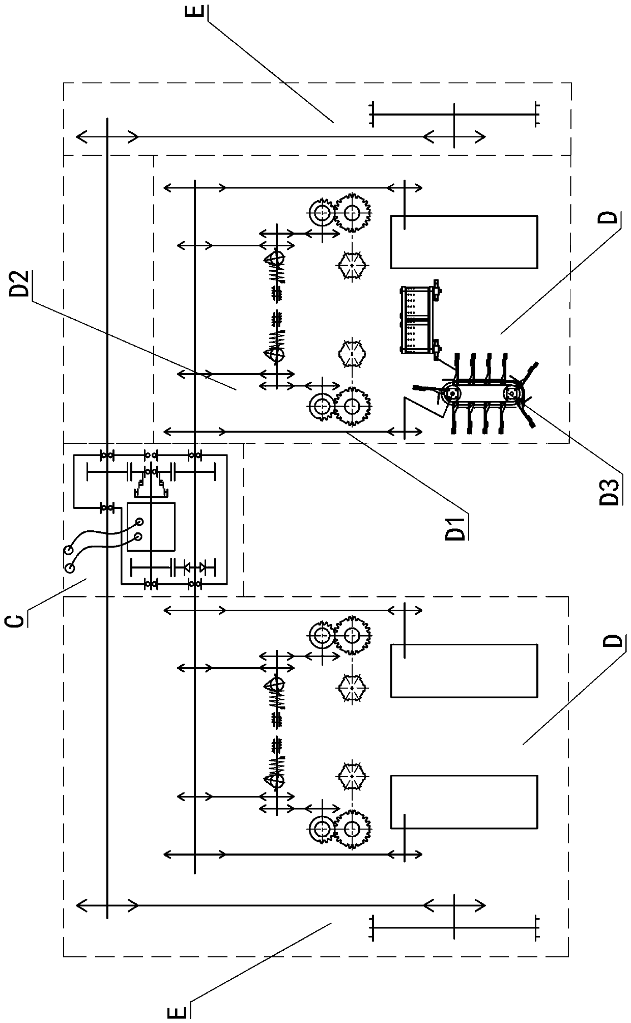
[0037] see Figure 1 to Figure 8 A power transmission system of a chain clamp type transplanter, comprising a planting device A, a frame B, a power confluence device C, a power transmission device D and a power input device E, a planting device A, a power confluence device C, and a power transmission device D and the power input device E are respectively installed on the frame B, and the power input device E is connected with the power confluence device C, and the power transmission device D is symmetrically arranged on both sides of the power confluence device C and connected with the power confluence device C, the specific structure is as follows:

[0038] The power confluence device C includes ground wheel input gear C1, intermediate gear C2,...


PUM


Abstract

The invention relates to a chain clamp type transplanting machine power transmission system. The chain clamp type transplanting machine power transmission system comprises a transplanting device, a power collector, power transmission devices and a power input device, wherein the power collector, the power transmission device and the power input device are mounted on a frame, the power input deviceis connected with the power collector, the power transmission devices are symmetrically arranged on two sides of the power collector and connected with the power collector, and an assistance drive device is arranged in the power collector. The chain clamp type transplanting machine power transmission system has the advantages that main power comes from ground wheel drive, assistance power comes from the external assistance drive device, high drive force and high synchronism are achieved, intermittent seedling tray conveying, whole-row ejection seedling taking, seedling clamp drive conveying belt conveying and seedling clamp lateral side transverse supply type seedling delivery are adopted, and the system is high in seedling taking efficiency, precise in seedling conveying, fast in seedling supply and especially suitable for high-speed transplanting machines.

Description

technical field [0001] The invention relates to the technical field of power transmission, in particular to a chain clamp type transplanter power transmission system. Background technique [0002] Transplanting at a high-speed transplanting machine, due to the influence of the speed of transporting seedlings, the transplanting speed has been difficult to improve. Different from the reciprocating planting method of the hanging cup type transplanting mechanism, the chain clip type transplanting mechanism adopts the method of continuously rotating the chain clip, which has the possibility of further improving the transplanting speed. The precision requirement is high, and it is difficult to mechanize and automatically release the seedlings. On the chain clip transplanter that uses manual seedlings, the transplanting speed is usually lower than 5000 plants / row / hour, which seriously affects the transplanting speed. Therefore, it is an important problem to be solved urgently for ...

Claims


Application Information

Patent Timeline
Patent Type & Authority Applications(China)
IPC IPC(8): A01C11/02F16H37/12
CPCA01C11/025F16H37/12
Inventor 孙松林肖名涛陈斌方芹刘奇
Owner HUNAN AGRICULTURAL UNIV
Why Eureka
Try Eureka