Dynamic tray

A tray and dynamic technology, applied in the field of seating, can solve the problems of complex installation, difficulty in mass production, and lack of versatility.

Inactive Publication Date: 2020-01-21
UE FURNITURE CO LTD
View PDF2 Cites 8 Cited by
  • Summary
  • Abstract
  • Description
  • Claims
  • Application Information

AI Technical Summary

Problems solved by technology

[0010] Although the above-mentioned seats can swing from side to side, they are equipped with a large number of rubber parts and a relatively complicated linkage mechanism, and the installation is also relatively complicated. The versatility is not enough, and it is difficult to achieve mass production

Method used


Image

  • Dynamic tray
  • Dynamic tray
  • Dynamic tray

Examples


Embodiment 1

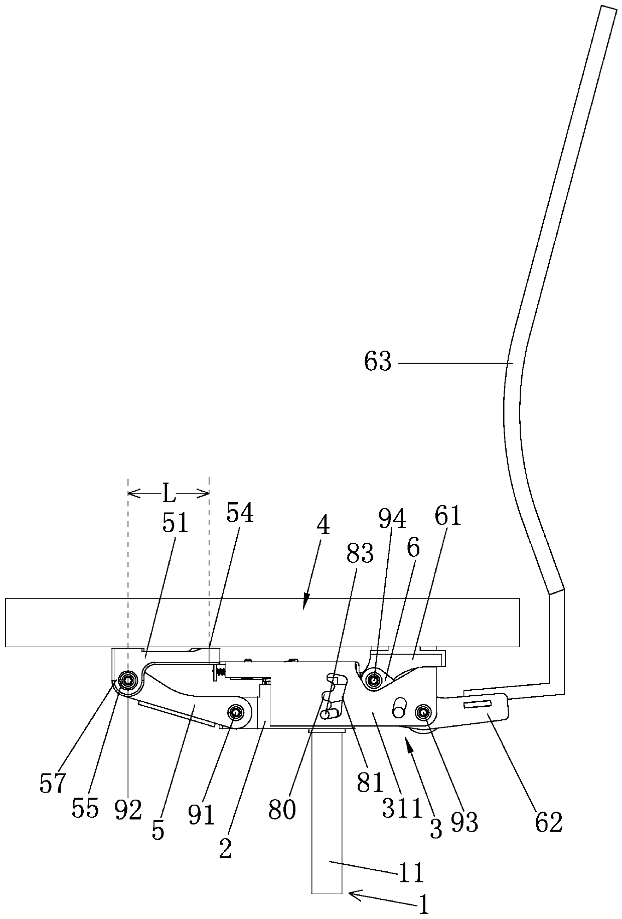
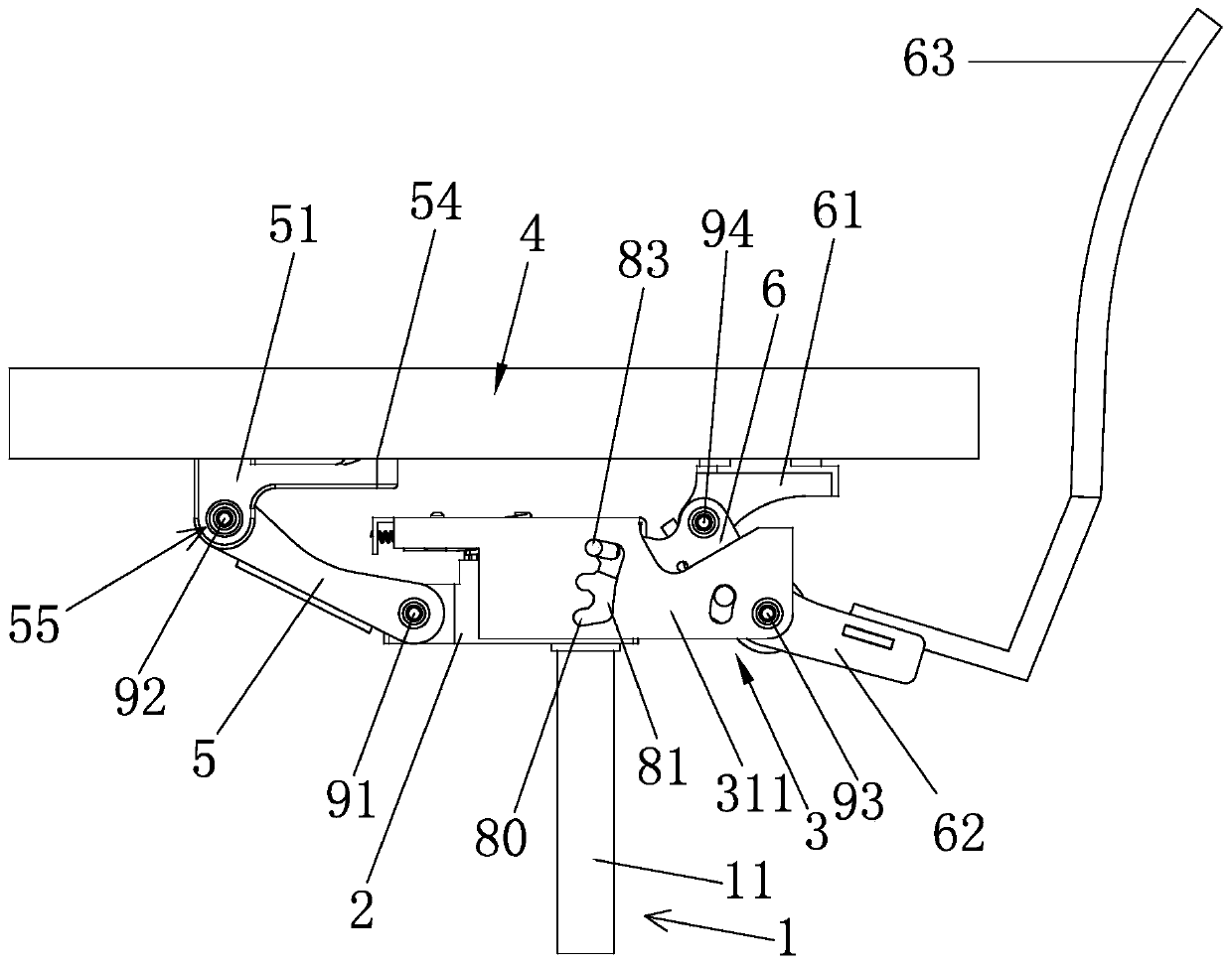
[0066] Embodiment 1: The dynamic tray of the present invention is an integral part of the dynamic seat, and the seat is described in detail next, so that the present invention and its application can be understood more clearly and appropriately; as Figure 1-18 As shown, the seat includes:

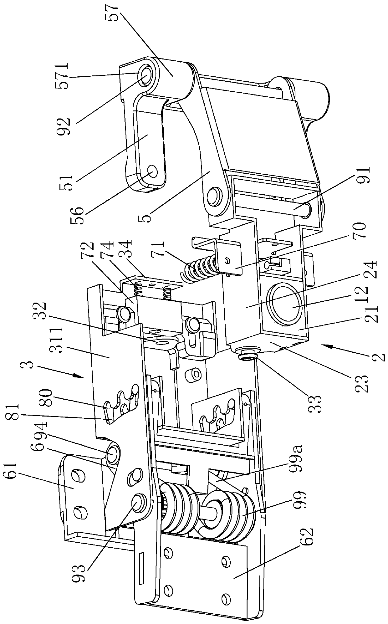
[0067] The first base 2 configured to connect the seat support assembly 1, the first base 2 includes a bottom plate 21 and a front plate 22 and a rear plate 23 extending upward from the front and rear ends of the bottom plate 21, the front plate 22 , The rear plate 23 plays a supporting role; the seat support assembly 1 includes a support rod 11 and a support foot (not shown), and a socket 12 is correspondingly provided on the bottom plate 21, and the support rod 11 is arranged in the socket 12 , the support rod 11 and the support feet are standing on the ground, so the first base 2 is kept horizontal and fixed relative to the ground except that it rotates in the circumferential direction,...

Embodiment 2

[0091] Embodiment 2: The difference with Embodiment 1 is that, as Figure 19 As shown, the two elastic transit connectors 51 in this embodiment are independent components, which is convenient for layout, and saves materials and reduces costs on the basis of meeting requirements.

Embodiment 3

[0092] Embodiment 3: The difference from Embodiment 1 is that the second base 3 rotates around the first base 2 through the rotating shaft 33, the rotating shaft 33 is a whole long axis, and the swing reset mechanism in this embodiment is sleeved The torsion spring (not shown) on the above-mentioned rotating shaft 33 has two torsion springs, one torsion arm of the torsion spring is connected to the base, and the other torsion arm of the torsion spring is connected to the left or right side of the top plate 31; it is realized by the torsion spring The rotation of the second base 3 resets.


PUM


Abstract

The invention relates to a dynamic tray comprising a first base, a second base, a first crank, a second crank, a warping plate and an elastic resetting device; the second base is rotatably connected to the left and the right of the first base; one end of the first crank is hinged to the first base, the other end of the first crank is hinged to an elastic transfer connecting piece, and the elastictransfer connecting piece is applied to a connecting seat supporting piece; the two ends of the second crank are hinged to the second base and a bearing piece respectively, the bearing piece is rigid,the bearing piece is applied to the connecting seat supporting piece, and the bearing piece is located at the upper end of the second base; the warping plate is configured to be connected with a chair back assembly, and the warping plate and the second crank are connected into a whole; and the elastic resetting device is used for enabling the second crank to restore the normal position after thewarping plate pries the second crank to move. According to the dynamic tray in the invention, a four-link principle is adopted for construction; the functions of lifting and left-right swinging of thechair seat are achieved simultaneously; and when a connecting seat is configured, the sitting posture changes of tilting back and forth and swinging left and right of a user can be automatically adapted to, the defects brought by long sitting are overcome, and the requirements of different people are met.

Description

technical field [0001] The invention relates to the field of seats, in particular to a dynamic tray. Background technique [0002] The seat chassis, also known as the seat tray, is an important part installed under the seat cushion. The lifting of the seat cushion and the adjustment of the tilt angle of the backrest are all done by the chassis. [0003] Since the human body will change various postures when sitting, it is necessary for the back of the chair to move back and forth following the back of the human body to make the back of the human body feel more comfortable; Adaptive seat. [0004] For example: Patent No. CN201320715928.9 discloses "a novel self-adaptive elastic seat", comprising a chair back frame, a headrest mounted on the top of the chair back frame, mounted on the chair back frame and positioned on the headrest As for the chair back below, the chair back includes a plurality of chair back strips, the chair back strips are independent of each other and ea...

Claims


Application Information

Patent Timeline
Patent Type & Authority Applications(China)
IPC IPC(8): A47C7/00A47C7/44A47C3/025A47C3/026A47C3/24
CPCA47C3/0255A47C3/026A47C3/24A47C7/004A47C7/44
Inventor 叶金金明华阮正富
Owner UE FURNITURE CO LTD
Why Eureka
Try Eureka